www.ti.com
Registers
4.3MMC Status Register 0 (MMCST0)
The MMC status register 0 (MMCST0) records specific events or errors. The transition from 0 to 1 on each bit in MMCST0 can cause an interrupt signal to be sent to the CPU. If an interrupt is desired, set the corresponding interrupt enable bit in the MMC interrupt mask register (MMCIM).
In most cases, when a status bit is read, it is cleared. The two exceptions are the DRRDY bit and the DXRDY bit; these bits are cleared only in response to the functional events described for them in Table 8, or in response to a hardware reset.
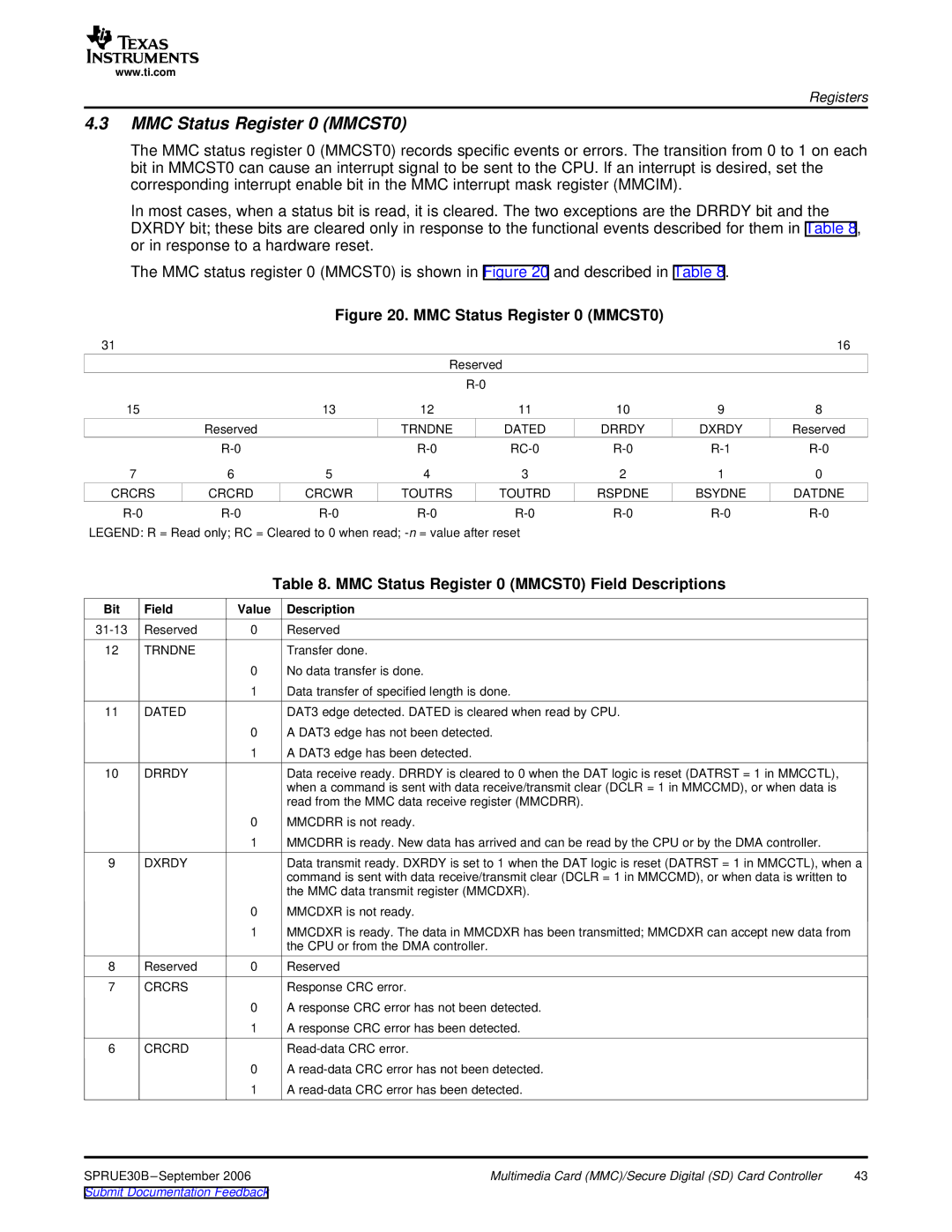
The MMC status register 0 (MMCST0) is shown in Figure 20 and described in Table 8.
Figure 20. MMC Status Register 0 (MMCST0)
31 |
|
|
|
|
|
| 16 |
|
|
| Reserved |
|
|
| |
|
|
|
|
|
|
| |
15 |
| 13 | 12 | 11 | 10 | 9 | 8 |
| Reserved |
| TRNDNE | DATED | DRRDY | DXRDY | Reserved |
|
| ||||||
7 | 6 | 5 | 4 | 3 | 2 | 1 | 0 |
CRCRS | CRCRD | CRCWR | TOUTRS | TOUTRD | RSPDNE | BSYDNE | DATDNE |
LEGEND: R = Read only; RC = Cleared to 0 when read; |
|
|
| ||||
|
|
| Table 8. MMC Status Register 0 (MMCST0) Field Descriptions |
Bit | Field | Value | Description |
Reserved | 0 | Reserved | |
12 | TRNDNE |
| Transfer done. |
|
| 0 | No data transfer is done. |
|
| 1 | Data transfer of specified length is done. |
11 | DATED |
| DAT3 edge detected. DATED is cleared when read by CPU. |
|
| 0 | A DAT3 edge has not been detected. |
|
| 1 | A DAT3 edge has been detected. |
10 | DRRDY |
| Data receive ready. DRRDY is cleared to 0 when the DAT logic is reset (DATRST = 1 in MMCCTL), |
|
|
| when a command is sent with data receive/transmit clear (DCLR = 1 in MMCCMD), or when data is |
|
|
| read from the MMC data receive register (MMCDRR). |
|
| 0 | MMCDRR is not ready. |
|
| 1 | MMCDRR is ready. New data has arrived and can be read by the CPU or by the DMA controller. |
9 | DXRDY |
| Data transmit ready. DXRDY is set to 1 when the DAT logic is reset (DATRST = 1 in MMCCTL), when a |
|
|
| command is sent with data receive/transmit clear (DCLR = 1 in MMCCMD), or when data is written to |
|
|
| the MMC data transmit register (MMCDXR). |
|
| 0 | MMCDXR is not ready. |
1MMCDXR is ready. The data in MMCDXR has been transmitted; MMCDXR can accept new data from the CPU or from the DMA controller.
8 | Reserved | 0 | Reserved |
7 | CRCRS |
| Response CRC error. |
|
| 0 | A response CRC error has not been detected. |
|
| 1 | A response CRC error has been detected. |
6 | CRCRD |
| |
|
| 0 | A |
|
| 1 | A |
SPRUE30B | Multimedia Card (MMC)/Secure Digital (SD) Card Controller | 43 |
Submit Documentation Feedback |
|
|