www.ti.com
Registers
4.13 MMC Command Register (MMCCMD)
Note: Writing to the MMC command register (MMCCMD) causes the MMC controller to send the programmed command. Therefore, the MMC argument register (MMCARGHL) must be loaded properly before a write to MMCCMD.
The MMC command register (MMCCMD) specifies the type of command to be sent and defines the operation (command, response, additional activity) for the MMC controller. The content of MMCCMD is kept after the transfer to the transmit shift register.
When the ARM writes to MMCCMD, the MMC controller sends the programmed command, including any arguments in the MMC argument register (MMCARGHL). For the format of a command (index, arguments, and other bits), see Figure 31 and Table 19.
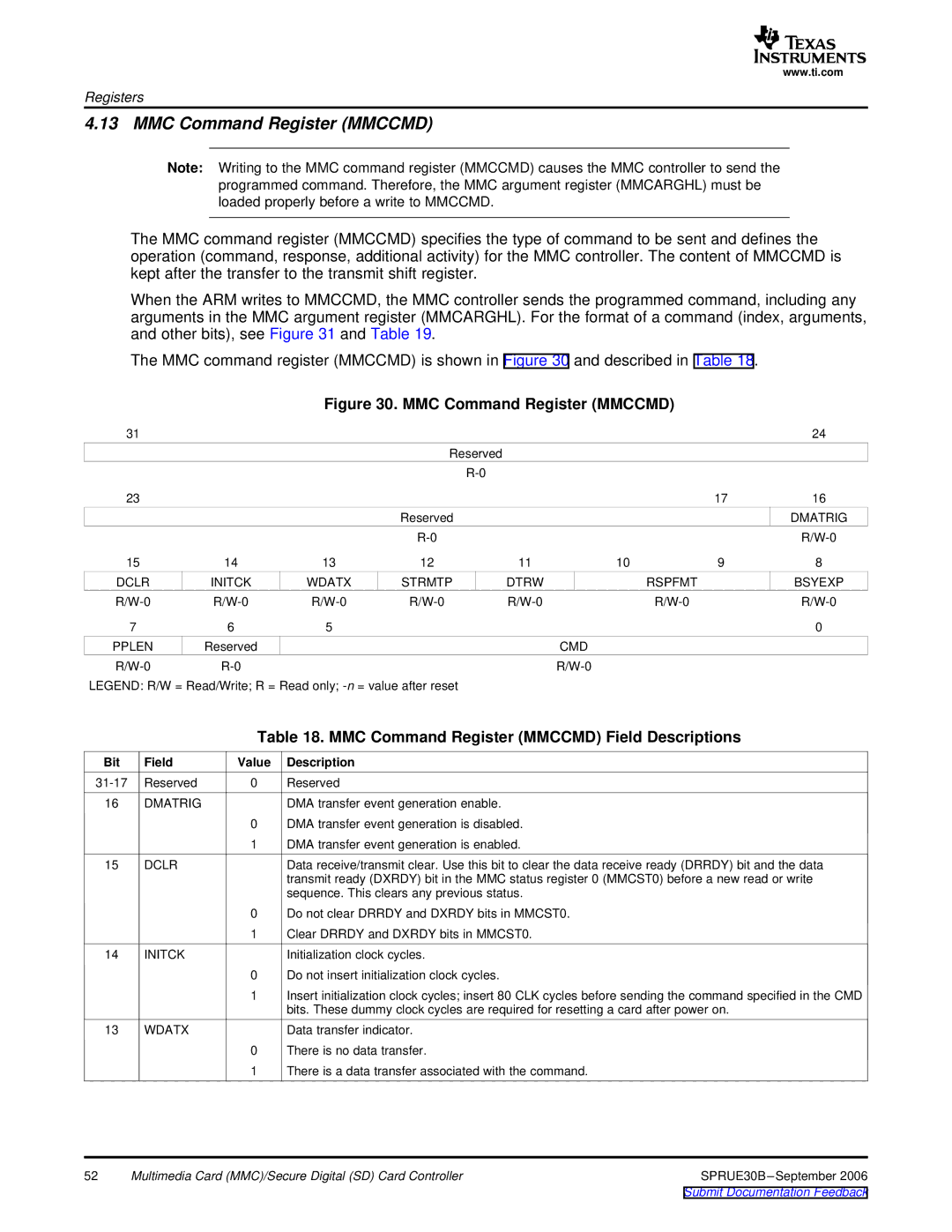
The MMC command register (MMCCMD) is shown in Figure 30 and described in Table 18.
Figure 30. MMC Command Register (MMCCMD)
31 |
|
|
|
|
|
| 24 |
|
|
| Reserved |
|
|
|
|
|
|
|
|
|
|
| |
23 |
|
|
|
|
| 17 | 16 |
|
|
| Reserved |
|
|
| DMATRIG |
|
|
|
|
|
| ||
15 | 14 | 13 | 12 | 11 | 10 | 9 | 8 |
DCLR | INITCK | WDATX | STRMTP | DTRW |
| RSPFMT | BSYEXP |
| |||||||
7 | 6 | 5 |
|
|
|
| 0 |
PPLEN | Reserved |
|
|
| CMD |
|
|
|
|
|
|
|
LEGEND: R/W = Read/Write; R = Read only;
Table 18. MMC Command Register (MMCCMD) Field Descriptions
Bit | Field | Value | Description |
Reserved | 0 | Reserved | |
16 | DMATRIG |
| DMA transfer event generation enable. |
|
| 0 | DMA transfer event generation is disabled. |
|
| 1 | DMA transfer event generation is enabled. |
15 | DCLR |
| Data receive/transmit clear. Use this bit to clear the data receive ready (DRRDY) bit and the data |
|
|
| transmit ready (DXRDY) bit in the MMC status register 0 (MMCST0) before a new read or write |
|
|
| sequence. This clears any previous status. |
|
| 0 | Do not clear DRRDY and DXRDY bits in MMCST0. |
|
| 1 | Clear DRRDY and DXRDY bits in MMCST0. |
14 | INITCK |
| Initialization clock cycles. |
|
| 0 | Do not insert initialization clock cycles. |
1Insert initialization clock cycles; insert 80 CLK cycles before sending the command specified in the CMD bits. These dummy clock cycles are required for resetting a card after power on.
13 | WDATX | Data transfer indicator. |
| 0 | There is no data transfer. |
| 1 | There is a data transfer associated with the command. |
52 | Multimedia Card (MMC)/Secure Digital (SD) Card Controller | SPRUE30B |