www.ti.com
Peripheral Architecture
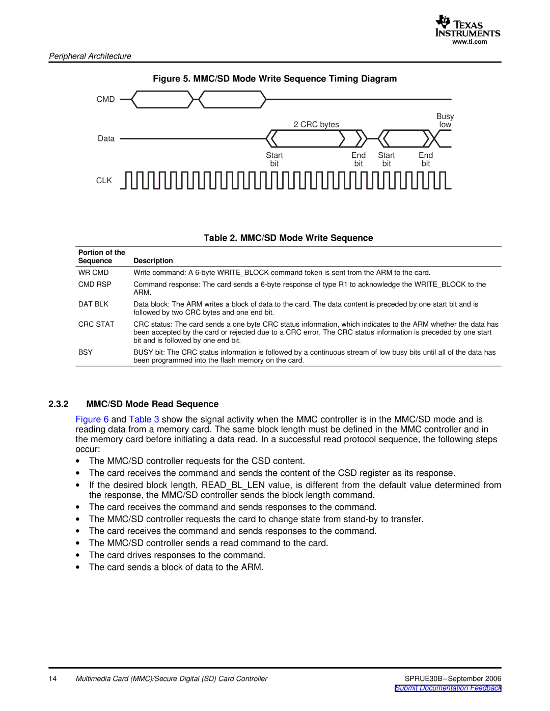
Figure 5. MMC/SD Mode Write Sequence Timing Diagram
CMD |
|
|
|
|
|
| Busy |
2 CRC bytes |
|
| low |
Data |
|
|
|
Start | End | Start | End |
bit | bit | bit | bit |
CLK
| Table 2. MMC/SD Mode Write Sequence |
Portion of the |
|
Sequence | Description |
WR CMD | Write command: A |
CMD RSP | Command response: The card sends a |
| ARM. |
DAT BLK | Data block: The ARM writes a block of data to the card. The data content is preceded by one start bit and is |
| followed by two CRC bytes and one end bit. |
CRC STAT | CRC status: The card sends a one byte CRC status information, which indicates to the ARM whether the data has |
| been accepted by the card or rejected due to a CRC error. The CRC status information is preceded by one start |
| bit and is followed by one end bit. |
BSY | BUSY bit: The CRC status information is followed by a continuous stream of low busy bits until all of the data has |
| been programmed into the flash memory on the card. |
2.3.2MMC/SD Mode Read Sequence
Figure 6 and Table 3 show the signal activity when the MMC controller is in the MMC/SD mode and is reading data from a memory card. The same block length must be defined in the MMC controller and in the memory card before initiating a data read. In a successful read protocol sequence, the following steps occur:
∙The MMC/SD controller requests for the CSD content.
∙The card receives the command and sends the content of the CSD register as its response.
∙If the desired block length, READ_BL_LEN value, is different from the default value determined from the response, the MMC/SD controller sends the block length command.
∙The card receives the command and sends responses to the command.
∙The MMC/SD controller requests the card to change state from stand-by to transfer.
∙The card receives the command and sends responses to the command.
∙The MMC/SD controller sends a read command to the card.
∙The card drives responses to the command.
∙The card sends a block of data to the ARM.
14 | Multimedia Card (MMC)/Secure Digital (SD) Card Controller | SPRUE30B |