TNETX4090
ThunderSWITCH II 9-PORT 100-/1000-MBIT/S ETHERNET SWITCH
SPWS044E ± DECEMBER 1997 ± REVISED AUGUST 1999
state of DIO signal terminals during hardware reset
The CPU can perform a hardware reset by writing to an address in the range of 0x40±0x5F (writes to a DMA address in this range have no effect on reset); this is equivalent to asserting the hardware RESET terminal with the following exceptions. During hardware reset, the output and bidirectional DIO terminals behave as shown in Table 7.
DDIO interface continues to operate. The reset condition remains active until SCS is driven high. SRDY does not become high impedance or resistively pulled high (unlike a true hardware reset), so it still can be used as a normal acknowledge in this case.
DFollowing the reset, no EEPROM autoload is performed.
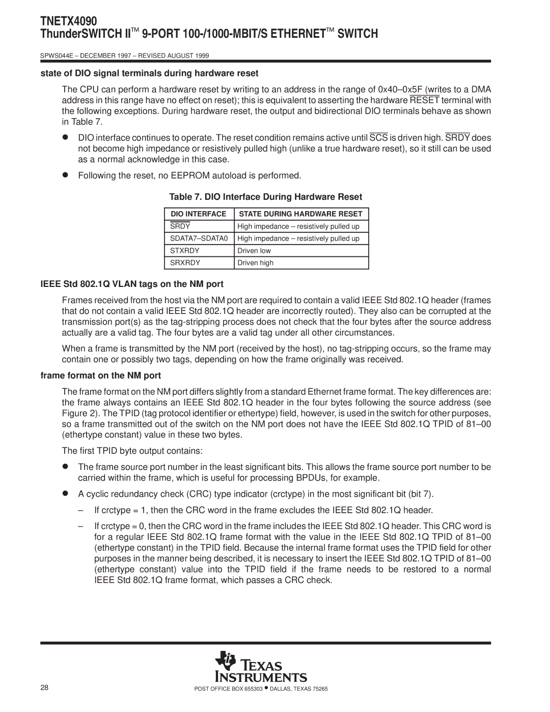
Table 7. DIO Interface During Hardware Reset
| DIO INTERFACE | STATE DURING HARDWARE RESET | |
|
| ||
|
|
| High impedance ± resistively pulled up |
| SRDY |
| |
|
| ||
SDATA7±SDATA0 | High impedance ± resistively pulled up | ||
|
| ||
STXRDY | Driven low | ||
|
| ||
SRXRDY | Driven high | ||
|
|
|
|
IEEE Std 802.1Q VLAN tags on the NM port
Frames received from the host via the NM port are required to contain a valid IEEE Std 802.1Q header (frames that do not contain a valid IEEE Std 802.1Q header are incorrectly routed). They also can be corrupted at the transmission port(s) as the
When a frame is transmitted by the NM port (received by the host), no
frame format on the NM port
The frame format on the NM port differs slightly from a standard Ethernet frame format. The key differences are: the frame always contains an IEEE Std 802.1Q header in the four bytes following the source address (see Figure 2). The TPID (tag protocol identifier or ethertype) field, however, is used in the switch for other purposes, so a frame transmitted out of the switch on the NM port does not have the IEEE Std 802.1Q TPID of 81±00 (ethertype constant) value in these two bytes.
The first TPID byte output contains:
DThe frame source port number in the least significant bits. This allows the frame source port number to be carried within the frame, which is useful for processing BPDUs, for example.
DA cyclic redundancy check (CRC) type indicator (crctype) in the most significant bit (bit 7).
±If crctype = 1, then the CRC word in the frame excludes the IEEE Std 802.1Q header.
±If crctype = 0, then the CRC word in the frame includes the IEEE Std 802.1Q header. This CRC word is for a regular IEEE Std 802.1Q frame format with the value in the IEEE Std 802.1Q TPID of 81±00 (ethertype constant) in the TPID field. Because the internal frame format uses the TPID field for other purposes in the manner being described, it is necessary to insert the IEEE Std 802.1Q TPID of 81±00 (ethertype constant) value into the TPID field if the frame needs to be restored to a normal IEEE Std 802.1Q frame format, which passes a CRC check.
28 | POST OFFICE BOX 655303 •DALLAS, TEXAS 75265 |