TNETX4090
ThunderSWITCH II 9-PORT 100-/1000-MBIT/S ETHERNET SWITCH
|
|
| SPWS044E ± DECEMBER 1997 ± REVISED AUGUST 1999 | ||
|
|
|
|
| |
|
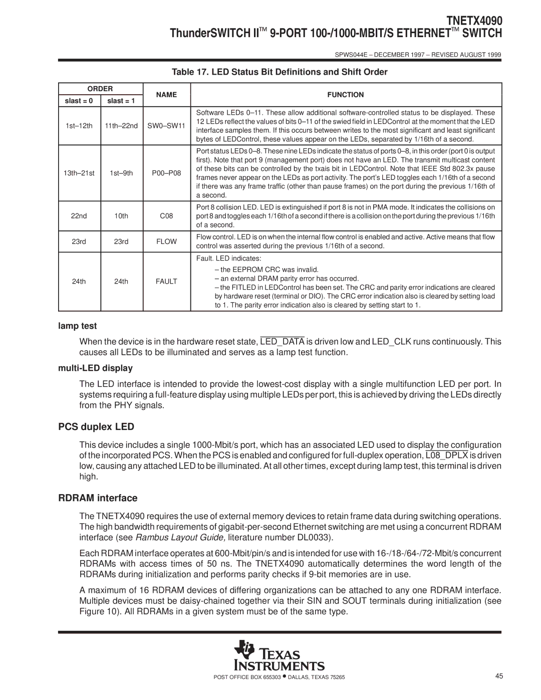
| Table 17. LED Status Bit Definitions and Shift Order | |||
|
|
|
|
| |
ORDER | NAME | FUNCTION |
| ||
|
|
| |||
slast = 0 | slast = 1 | ||||
|
|
| |||
|
|
|
|
| |
|
|
| Software LEDs 0±11. These allow additional |
| |
1st±12th | 11th±22nd | SW0±SW11 | 12 LEDs reflect the values of bits 0±11 of the swied field in LEDControl at the moment that the LED |
| |
interface samples them. If this occurs between writes to the most significant and least significant |
| ||||
|
|
|
| ||
|
|
| bytes of LEDControl, these values appear on the LEDs, separated by 1/16th of a second. |
| |
|
|
|
|
| |
|
|
| Port status LEDs 0±8. These nine LEDs indicate the status of ports 0±8, in this order (port 0 is output |
| |
|
|
| first). Note that port 9 (management port) does not have an LED. The transmit multicast content |
| |
13th±21st | 1st±9th | P00±P08 | of these bits can be controlled by the txais bit in LEDControl. Note that IEEE Std 802.3x pause |
| |
frames never appear on the LEDs as port activity. The port's LED toggles each 1/16th of a second |
| ||||
|
|
|
| ||
|
|
| if there was any frame traffic (other than pause frames) on the port during the previous 1/16th of |
| |
|
|
| a second. |
| |
|
|
|
|
| |
|
|
| Port 8 collision LED. LED is extinguished if port 8 is not in PMA mode. It indicates the collisions on |
| |
22nd | 10th | C08 | port 8 and toggles each 1/16th of a second if there is a collision on the port during the previous 1/16th |
| |
|
|
| of a second. |
| |
|
|
|
|
| |
23rd | 23rd | FLOW | Flow control. LED is on when the internal flow control is enabled and active. Active means that flow |
| |
control was asserted during the previous 1/16th of a second. |
| ||||
|
|
|
| ||
|
|
|
|
| |
|
|
| Fault. LED indicates: |
| |
|
|
| ± the EEPROM CRC was invalid. |
| |
24th | 24th | FAULT | ± an external DRAM parity error has occurred. |
| |
± the FITLED in LEDControl has been set. The CRC and parity error indications are cleared |
| ||||
|
|
|
| ||
|
|
| by hardware reset (terminal or DIO). The CRC error indication also is cleared by setting load |
| |
|
|
| to 1. The parity error indication also is cleared by setting start to 1. |
| |
|
|
|
|
| |
lamp test
When the device is in the hardware reset state, LED_DATA is driven low and LED_CLK runs continuously. This causes all LEDs to be illuminated and serves as a lamp test function.
multi-LED display
The LED interface is intended to provide the
PCS duplex LED
This device includes a single
RDRAM interface
The TNETX4090 requires the use of external memory devices to retain frame data during switching operations. The high bandwidth requirements of
Each RDRAM interface operates at
A maximum of 16 RDRAM devices of differing organizations can be attached to any one RDRAM interface. Multiple devices must be
POST OFFICE BOX 655303 •DALLAS, TEXAS 75265 | 45 |