TNETX4090
ThunderSWITCH II 9-PORT 100-/1000-MBIT/S ETHERNET SWITCH
SPWS044E ± DECEMBER 1997 ± REVISED AUGUST 1999
EEPROM interface (continued)
After the initial start condition, a slave address containing a device address of 000 is output on EDIO, and then EDIO is observed for an acknowledge from the EEPROM. If an acknowledge is received, operation continues for the 24C02 EEPROM. If none is received, a stop condition is generated, followed by another start condition and slave address, this time containing a device address of 101. If this receives no acknowledge, no EEPROM is present, and device operation continues, using the current register settings (i.e., those following a hardware reset, or those previously entered by software).
When this device is driving EDIO, it drives out only a strong logical 0. When a logical 1 is intended to be driven out, the terminal must be resistively pulled high. An
Multiple bus masters are not supported on the EEPROM interface because the ECLK terminal always is driven by the device with a strong 0/strong 1 (i.e., not a strong 1/resistively
An Ethernet CRC check is used to ensure the EEPROM data is valid. The
A valid CRC always must be provided by the EEPROM. The EEPROM data for the most significant bit of SysControl is withheld until the CRC computed by the device has been checked against the one read from the EEPROM. If the CRC is invalid:
DThe reset bit is set to 1 in SysControl, load and initd are both 0, and the TNETX4090 does not begin operation.
DThe fault LED is illuminated and remains in that state until the TNETX4090 is hardware reset or until load in SysControl is set to 1.
interaction of EEPROM load with the SIO register
The EDIO terminal is shared with the SIO register edata bit. The edata and etxen bits must not both be set to 1 when the load bit is set or the EDIO terminal is held at resistive 1 and the EEPROM load fails.
The value of the eclk bit in SIO is don't care when load is set, but to ensure the EEPROM does not see a glitch on its clock signal, the load bit should not be set until the minimum clock high or low time required by the EEPROM on its clock signal has expired since the eclk bit was last changed.
The SIO register is not loaded during the EEPROM download.
summary of EEPROM load outcomes
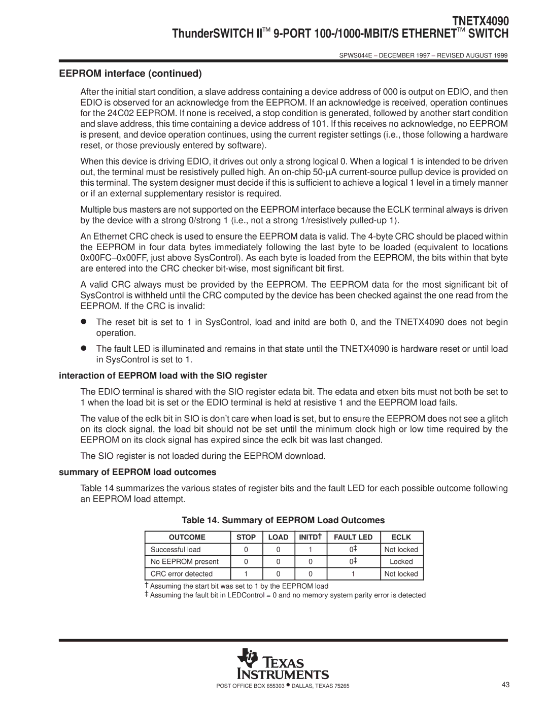
Table 14 summarizes the various states of register bits and the fault LED for each possible outcome following an EEPROM load attempt.
Table 14. Summary of EEPROM Load Outcomes
OUTCOME | STOP | LOAD | INITD² | FAULT LED | ECLK |
Successful load | 0 | 0 | 1 | 0³ | Not locked |
No EEPROM present | 0 | 0 | 0 | 0³ | Locked |
CRC error detected | 1 | 0 | 0 | 1 | Not locked |
|
|
|
|
|
|
² Assuming the start bit was set to 1 by the EEPROM load
³Assuming the fault bit in LEDControl = 0 and no memory system parity error is detected
POST OFFICE BOX 655303 •DALLAS, TEXAS 75265 | 43 |