Appendix F Wiring Diagrams
F.1 LAN Loopback Connector
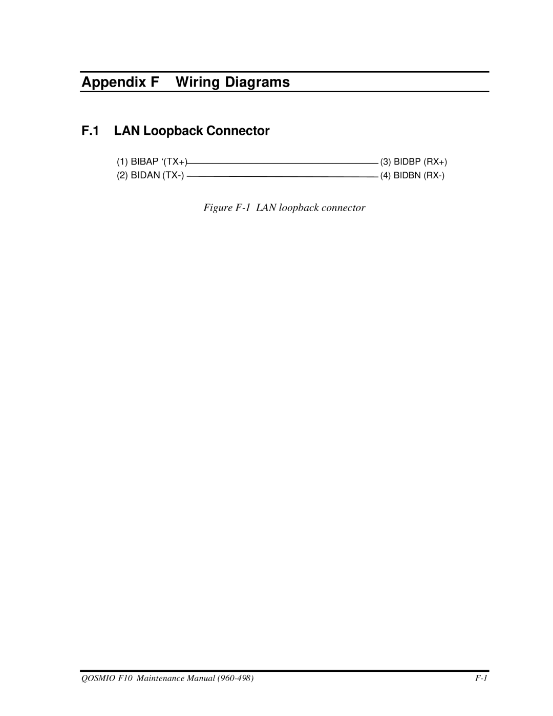
(1) | BIBAP ‘(TX+) |
| (3) BIDBP (RX+) |
| |||
(2) | BIDAN | (4) BIDBN | |
Figure F-1 LAN loopback connector
QOSMIO F10 Maintenance Manual |
(1) | BIBAP ‘(TX+) |
| (3) BIDBP (RX+) |
| |||
(2) | BIDAN | (4) BIDBN | |
QOSMIO F10 Maintenance Manual |