Acutime 2000 Synchronization Kit
Timing and Synchronization Group
Software and Firmware License, Limited Warranty
Limitation of Liability
Contents
Acutime 2000 Installation
NTP Software Installation and Configuration
Trimble Standard Interface Protocol
Timing Receiver Monitor
Glossary Index
List of Figures
Page
List of Tables
List of Tables
List of Tables
Xvi Acutime 2000 Synchronization Kit User Guide
Acutime 2000 Synchronization Kit User Guide Xvii
Page
Scope and Audience
About This Manual
Organization
Reader Feedback
Update Notes
Related Information
World Wide Web WWW Site
Abbreviations
Document Conventions
Technical Assistance
Page
Overview
Introduction
Acutime 2000 GPS Smart Antenna Features
Acutime 2000 GPS Smart Antenna Enclosure
Starter Kit
Getting Started
Connecting the Smart Antenna
Connection Diagram
Connecting the Computer and Power Source
Communicating with the Acutime
Acutime 2000 Installation
Mounted Antenna
Choosing a Location
Acutime 2000 Installation
Mounting the Smart Antenna
Routing and Securing the Interface Cable
Connecting the Host System
Acutime 2000 Connections
Acutime 2000 Interface Connector
Interface and Power Connections
Acutime 2000 12-pin Connector format
Interface Cables and Connectors
Mating Connectors
Antenna Mating Manufacturer Description Connector
Signal Description Wire Color Protocol Acutime Connector
Pin-Outs
Acutime 2000 RS-422 Cable Pin-Out
Acutime 2000 RS-232 Cable Pin-Out
Power Connection Red and Black Wires
Connection Instructions
Timing Pulse Connections
Port B
Serial Port Connections
Port a
Event Input
Page
Start-Up
System Operation
Mask Setting
Default Satellite Mask Settings
Automatic Operation
Satellite Masks
Pdop Mask
SNR Mask
Tracking Modes
Self-Survey Mode
Overdetermined Clock Mode
PPS Output Options
PPS Quantization Error
PPS Quantization Error
Removing the Quantization Error from the PPS Output
External Event Input
Cable Delay Compensation
Serial Data Communication
Port B
Port a Timing
System Operation
GPS Timing
Timing Operation
Timing Pulse Output PPS
Using the Acutime 2000 in Mobile Applications
Customizing Acutime 2000 Operations
Receiver Configuration segment
OEM Configuration segment
Parameter Factory default Set Request Report
Port a and B Configuration segment
PPS Configuration segment
Position Information segment
Nmea Configuration segment
Parameter Factory default Set Request Report Haveutc
UTC Information segment
System Operation Acutime 2000 Synchronization Kit User Guide
Network Time Protocol
NTP Software Installation and Configuration
NTP Time Server Requirements
NTP Time Servers
Software Sources and Compatibility
Installation Support
Pre-Installation Check List
GPS Preparation
Host System Preparation
Operating System Specific Information
Time Transfer Cable Connection
Time Transfer Connection Diagram
Optional Connections
NTP Software Installation
NTP Configuration File
NTP Configuration File
Unit Number
Acutime Configuration
Network Server Selection
Additional Configuration Information
Windows NT Installation
Automatic Installation
Create the Configuration File
Manual Installation
NTP Software Installation and Configuration
Copying Executable Files
Copy NTPQ.EXE, NTPDATE.EXE, NTPDC.EXE, NTPTRACE.EXE
Type instsrv c\winnt\system32\ntpd.exe
Installing the Service
Page
Starting the Service
Unix Installation
Create the Configuration File
Cd /dev Ln -s ttyS0 /dev/Acutime0
Set Up Device Links
Hpux
System Serial Ports and Symbolic Link Names
Disabling Serial Port Services Using an Administrative Tool
Hardware Configuration
Copying Executable Files
System Initialization
Start NTP
Monitoring NTP
Event Log Entries
NTP Events on Windows NT
NTP Software Installation and Configuration
Sample Unix Log Entries
Unix System Log Files
Ntpq The NTP Query Utility
Acutime NTP reference clock is identified in the list as
NTP is Communicating with the Acutime NTP Reference Clock
No Response from the Acutime NTP Reference Clock
NTP is not Running
NTP Software Installation and Configuration
Interface Scope
Trimble Standard Interface Protocol
Packet Structure
Physical Interface Characteristics
Protocol Capabilities
Nomenclature
Table A-1 Ace UTC Port Translation Table
Table A-2
Secondary Port Features Acutime
Primary Port Features
Table A-3 Secondary Port Features Acutime
Event Input
Secondary Port Features Ace UTC
Packets Output at Power-Up
Table A-4 Secondary Port Features Ace UTC
Event Reporting Table A-5 Event Packets
Table A-7 Receiver Warm Start Commands
Table A-6 Packets Output at Power-Up
Receiver Warm Start
Output ID Description
Table A-8 Background Packets
Default Background Packets for Acutime
Table A-9 Automatic position and Velocity Reports
Default Automatic Position and Velocity Reports for Acutime
Low-Latency Timing Packets
Table A-10 Low-Latency Timing Packets
Lltp Packet ID Description Request Packet ID
Satellite Data Packets
Event Packets
Table A-11 Satellite Data Packets
Input ID Description Output ID
Table A-12 Customizing Receiver Operations
Customizing Receiver Operations
Table A-13 Advanced Packets
Command Packets Sent to the Receiver
Table A-14 Command Packets Sent to the Receiver
Input Packet Description Output ID
8E-AB
Report Packets Sent by the GPS Receiver to the User
Table A-15 Report Packets Sent by GPS Receiver to User
Output ID Packet Description Input
ATrimble Standard Interface Protocol
8F-AD
DLE id data string bytes DLE ETX
Packet Structure
Table A-17 Command Packet 1D Set Oscillator Offset
Table A-16 Command Packet 1D Clear Oscillator Offset
Packet Descriptions
Oscillator Offset
Table A-18 Command Packet 1E
Initiate Cold or Factory Reset
0x1E Command Packet 1E
0x1F Command Packet 1F
Table A-19 Command Packet
Initial Position XYZ Cartesian Ecef Command
0x20 0x21 0x23
Almanac Request
Initiate Soft Reset / Self Test Command
GPS Receiver Position Fix Mode Request
0x24 0x25
Health Request
Altitude for 2-D Mode Command
Signal Levels Request
0x27 0x28 0x29 0x2A
GPS System Message Request
Trimble Standard Interface Protocol
Table A-20 Command Packet 2B
Initial Position Latitude, Longitude, Altitude Command
0x2B 0x2D
Oscillator Offset Request
Accurate Initial Position XYZ Cartesian Ecef Command
GPS Time Command
Table A-21 Command Packet 2E
0x2E 0x2F 0x31
Trimble Standard Interface Protocol
0x32 0x34
Satellite Number For One-Satellite Mode Command
0x35 Command Packet
Option Flags Command
Table A-22 Command Packet
Byte
Bytes
Trimble Standard Interface Protocol
Byte
0x37 0x38
Last Position and Velocity Request
Download and UpLoad Satellite System Data
Byte Type Value Meaning
Table A-23 Command Packet
Satellite Attribute Database Command
Table A-24 Command Packet
0x39 Command Packet
Table A-26 Command Packet 3B
Table A-25 Command Packet 3A
Last Raw Measurement Request
Satellite Ephemeris Status Request
Table A-27 Command Packet 3C
0x3C Command Packet 3C
Satellite Tracking Status Request
Eeprom Segment Commands
Timing Port Configuration Command
Table A-28 Command Packet 3F-11
Almanac Data Page Report
GPS Time Report
0x41
Table A-30 Report Packet
Report Packet
Table A-31 Relationship Between Packet 41 and Packet
Approximate Time Time Source Sign Packet Accuracy
Status Code
Single-Precision Position Fix, XYZ Ecef Report
Table A-32 Report Packet
0x42 Report Packet
Velocity Fix, XYZ Ecef Report
Table A-33 Report Packet
0x43 Report Packet
Table A-34 Report Packet
Software Version Information Report
0x45 Report Packet
Byte Type
Health of Receiver Report
Table A-35 Report Packet
0x46 Report Packet
Table A-36 Report Packet
Error Code Meaning if bit value = Bit Position
0x47 0x48
Signal Levels for all Satellites Report
GPS System Message Report
Table A-37 Report Packet
Almanac Health Page Report
0x49 0x4A
Table A-38 Report Packet
Table A-39 Report Packet 4A Report Reference Altitude
Latitude
Machine/Code ID and Additional Status Report
Table A-41 Report Packet 4B
Table A-42 Byte 1 Bit Encoding Status
Operating Parameters Report
Byte Type, Units Default Value, Velocity
Table A-43 Report Packet 4C
0x4C Report Packet 4C
0x4D 0x4E
GPS Time Change Acknowledgment
Table A-44 Report Packet 4E
Table A-45 Report UTC Parameters
UTC Parameters Report
0x4F Report Packet 4F
Byte Value Type
Option Flags Report
Bias and Bias Rate Report
Table A-46 Report Packet
0x54 Report Packet
Velocity Fix, East-North-Up ENU Report
Table A-47 0x56 Velocity Fix, East-North-Up ENU Report
0x56 Report Packet
Table A-48 Report Packet
Information About Last Computed Fix Report
0x57 Report Packet
Byte Type/Units Value
Satellite System Data/Acknowledge from Receiver
Table A-49 Report Packet
0x58 Report Packet
Byte Type Meaning
Table A-50 Report Packet 58 Almanac Data Report
Table A-52 Report Packet 58 Ionosphere Data Report
Table A-51 Report Packet 58 Almanac Health Data Report
Table A-54 Report Packet 58 Ephemeris Data Report
Table A-53 Report Packet 58 UTC Data Report
Iode Byte
Satellite Attributes Database Report
Table A-55 Report Packet
0x59 Report Packet
Raw Measurement Data Report
0x5A
Table A-56 Report Packet 5A
Report Packet 5A
Signal level
Codephase
Doppler
Satellite Ephemeris Status Report
Time of measurement
0x5B Report Packet 5B
Table A-57 Report Packet 5B
Table A-58 Report Packet 5C
Satellite Tracking Status Report
0x5C Report Packet 5C
Byte/Item Type/Units Value/Meaning
Approximate elevation of this satellite
Eeprom Segment Status Reports
0x5F-11
Table A-59 Report Packet 5F-11 Eeprom Segment Status Report
Report Packet 5F-11
Type 1 Differential GPS Corrections
0x60 Command Packet
Table A-60 Report Packet 0x60 Data Formats
Byte Bit Type Range Units
SV PRN
Byte Bit Type Value Definition
Table A-62 Command Packet 0x61 Data Formats
0x61 Command Packet
Set Differential GPS Corrections
All-In-View Satellite Selection Report
Table A-63 Report Packet 6D
0x6D Report Packet 6D
Table A-64 Command Packet 7A
0x7A Command Packet 7A
Set or Request Nmea Interval and Message Mask
Nmea Message Output
0x7B 0x83
Double-precision XYZ Position Fix And Bias Information
Table A-65 Report Packet
Double-precision LLA Position Fix and Bias Information
Table A-66 Report Packet
0x84 Report Packet
Table A-67 Survey State Configurations
Set Primary Receiver Configuration
0xBB Command Packet BB
Survey State Active Configuration
Dynamics Code
Table A-68 Vaild GPS Configuration Settings
Signal Level Mask
Table A-69 Pdop Mask and Switch
Command Packet BB
Byte # Type Value Meaning Default
Table A-69 Command Packet BB
Set Port Configuration Parameters
Report Receiver Configuration
Table A-70 Command Packet BC
0xBC Command Packet BC
0xBC Report Packet BC
Request Port Configuration Parameters
Tsip Superpackets
Custom OEM Packets
Request or Configure Super Packet Output
Command Packet 8E-0B
0x8E-0B
Command Packet 8E-14
Table A-71 Command Packet 8E-14
0x8E-14
Set New Datum
Command Packet 8E-15
Table A-72 Command Packet 8E-14
0x8E-15
Request Current Datum Values
0x8E-20
0x8E-26
0x8E-41
Table A-74 Command Packet 0x8E-45
Revert Segments to Default Settings
0x8E-42
0x8E-45
Table A-75 Command Packet 8E-4A
Set/Request PPS Characteristics
Command Packet 8E-4A
0x8E-4A
Command Packet 8E-4D
Table A-76 Command Packet 8E-4D
0x8E-4D
Automatic Packet Output Mask
Bit # Output Default When Meaning Packets
Table A-77 Command Packet 8E-4D Packets Affected By Bits
Command Packet 8E-4E
0x8E-4E
Set PPS Output Option
0x8E-A5
0x8E-4F
Set PPS Width
Set or Request Packet Broadcast Mask
Trimble Standard Interface Protocol
Byte Bit Type Default Description
Table A-80 Command Packet 8E-A5
0x8E-A6
Issue Self-Survey Command
0x8E-A9
Set Self-Survey Parameters
Command Packet 8E-A9 Data Format segment
Table A-82
Byte Type Value Description
Command Packet 8E-AB
Table A-83 Command Packet 8E-AB
0x8E-AB
Request Primary Timing Packet
Command Packet 8E-AC
Table A-84 Command Packet 8E-AC
0x8E-AC
Request Supplemental Timing Packet
0x8E-AD
Command Packet 8E-AD Acutime 2000 only
Comprehensive Time
0x8F-0B
Table A-85 Report Packet 8F-0B
Report Packet 8F-0B
38-41 Oscillator Drift
Current Datum Values
0x8F-14
Table A-86 Report Packet 8F-14
Report Packet 8F-14
Last Fix with Extra Information binary fixed point
00x8F-20
Table A-87 Report Packet 8F-20
Report Packet 8F-20
Bytes Item/Type Meaning 32-47
Table A-88 Report Packet 8F-20
Response to Save Eeprom Segments
0x8F-26
Table A-89 Report Packet 0x8F-26
Report Packet 0x8F-26
Manufacturing Parameters
0x8F-41
Table A-90 Report Packet 8F-41
Report Packet 8F-41
0x8F-45
0x8F-42
Table A-91 Report Packet 8F-42
Report Packet 8F-42
Table A-92 Command Packet 8E-AD
Command Packet 8E-AD Request 8F-AD
Byte # Type Value Default Meaning
0x8F-4A
PPS Characteristics
Table A-93 Report Packet 8F-4A
Report Packet 8F-4A
0x8F-4D
Bit # Output When Output Meaning Packets
Table A-94 Report Packet 8F-4D
Table A-95 Report Packet 8F-4D
0x8F-A5
0x8F-4E
Report Packet 0x8F-4E
Report Packet 8F-A5
0x8F-A6
0x8F-A9
0x8F-AB
116 Acutime 2000 Synchronization Kit User Guide
UTC Integer
Table A-96 Report Packet 0x8F-AB
Report Packet 8F-AC
0x8F-AC
Acutime 2000 Synchronization Kit User Guide 119
120 Acutime 2000 Synchronization Kit User Guide
GPS Byte
Table A-97 Report Packet 8F-AC
Reserved 16-19 Bias
Primary UTC Time
0x8F-AD
Table A-98 Report Packet 8F-AD
Report Packet 8F-AD
Flag Value Status Meaning
Table A-99 Tracking Status Flag Definitions
Table A-100 Leap Second Flag Definitions
Leap Second Flag
Bit # Name Meaning if set to
Datums
Table A-101 Datums
Index Axis Eccentricity Description
Acutime 2000 Synchronization Kit User Guide 127
128 Acutime 2000 Synchronization Kit User Guide
Acutime 2000 Synchronization Kit User Guide 129
130 Acutime 2000 Synchronization Kit User Guide
Acutime 2000 Synchronization Kit User Guide 131
132 Acutime 2000 Synchronization Kit User Guide
Acutime 2000 Synchronization Kit User Guide 133
Sample Tsip Routines
Sending out Tsip command packet 0x1F
Acutime 2000 Synchronization Kit User Guide 135
Handling incoming Tsip packet
Acutime 2000 Synchronization Kit User Guide 137
Page
Timing Receiver Monitor
Main screen
Nmea
Signal Characteristic Nmea Standard
Table C-1 Nmea 0183 Characteristics
Nmea 0183 Communication Interface
Nmea 0183 Message Format
Each message contains multiple data fields Dn
Setting Message Description
Nmea 0183 Message Options
Table C-2 Acutime 2000 Nmea Messages
GGA GPS Fix Data
Nmea 0183 Message Formats
Table C-3 GGA GPS Fix Data Message Parameters
Field Description
Field # Description
GLL Geographic Position Latitude/Longitude
GSA GPS DOP and Active Satellites
Table C-6 GSV GPS Satellites in View Message Parameters
GSV GPS Satellites in View
RMC Recommended Minimum Specific GPS/Transit Data
VTG Track Made Good and Ground Speed
Table C-9 ZDA Time & Date Message Parameters
ZDA Time & Date
Nmea Acutime 2000 Synchronization Kit User Guide
Table D-1 Physical Specifications
Acutime 2000 GPS Smart Antenna Specifications
Dimensions
Weight
Table D-3 Performance Specifications
Table D-2 Environmental Specifications
Table D-4 Electrical Specifications
Table D-5 Serial Protocols
Port Interface Protocols Defaults
Acutime 2000 Standard Interface Cable Diagram
Figure D-1 Acutime 2000 Standard Interface Cable
Figure D-2 NTP Interface Cable
Specifications and Drawings
System Log Entries
Diagnostics and Debugging
Serial Port Acces Report
Configuration File Not Found
Error Log Entries
Acutime 2000 Synchronization Kit User Guide
Acutime Configuration Failure
COM Port Unavailable
System Clock Not Set
Running NTP in Debug Mode
NTP Startup and Acutime Poll
Debug Mode Not Available
NTP Diagnostics and Debugging
Acutime is not Responding
Running NTP with Event Polling Disabled
Table E-1 Troubleshooting Acutime is Not Responding
Possible Problem Solution
Fudge 127.127.127.x flag2
Palisadepoll unit x polling synchronous packet
Incorrect Port and Bad Data
Table E-2 Troubleshooting Incorrect Port and Bad Data
Serial Port is Unavailable
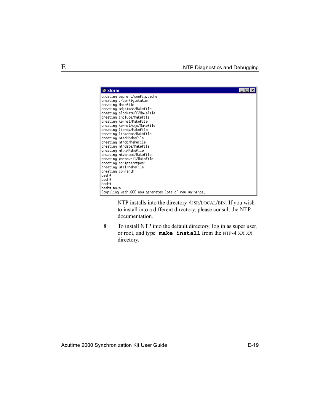
Compiling the NTP Distribution
NTP Diagnostics and Debugging
NTP Diagnostics and Debugging
NTP Diagnostics and Debugging
Controlling the NTP Service Removing the NTP Service
Windows NT Administration
Type instsrv remove
Additional Information
Page
Theory of Operation
GPS Satellite Message
Cold Start
Satellite Acquisition and Time to First Fix
Warm Start
Hot Start
Garage Search Strategy
Selective Availability S/A
Position Accuracy
Coordinate Systems
Tsip
Nmea
Update Rate
Performance Characteristics
Dynamic Limits
Re-Acquisition
Theory of Operation
Figure F-2
System Architecture
Figure F-1 Acutime 2000 Block Diagram RS-232 Version
Page
Glossary
Ascii
DCE
DOP
Elevation mask
Gdop
GPS
Iode
Pdop
ROM
SEP
SPS
Index
Index-2
Acutime 2000 Synchronization Kit User Guide Index-3
Index-4 Acutime 2000 Synchronization Kit User Guide
Reader Comment Form