Modulation mode
These commands allow you to select the modulation mode between amplitude, frequency and phase modulation as well as binary
Quadrature FSK is achieved using both the TRIGGER INPUT and PULSE INPUT sockets. Also pulse modulation may be selected from a signal connected to the PULSE INPUT socket. These modulations may be used in the combinations shown in the table below. Additionally, an external signal applied to the EXT MOD INPUT socket can be combined with any selected modulation combination.
MODE | Set modulation mode |
Data type : Character Program Data (valid combinations of AM, FM, PM, FSK2L,
FSK4L or PULSE. See table below.)
Allowed suffices : None
Default suffix : None
Examples: MODE AM,FM
MODE FM,PULSE
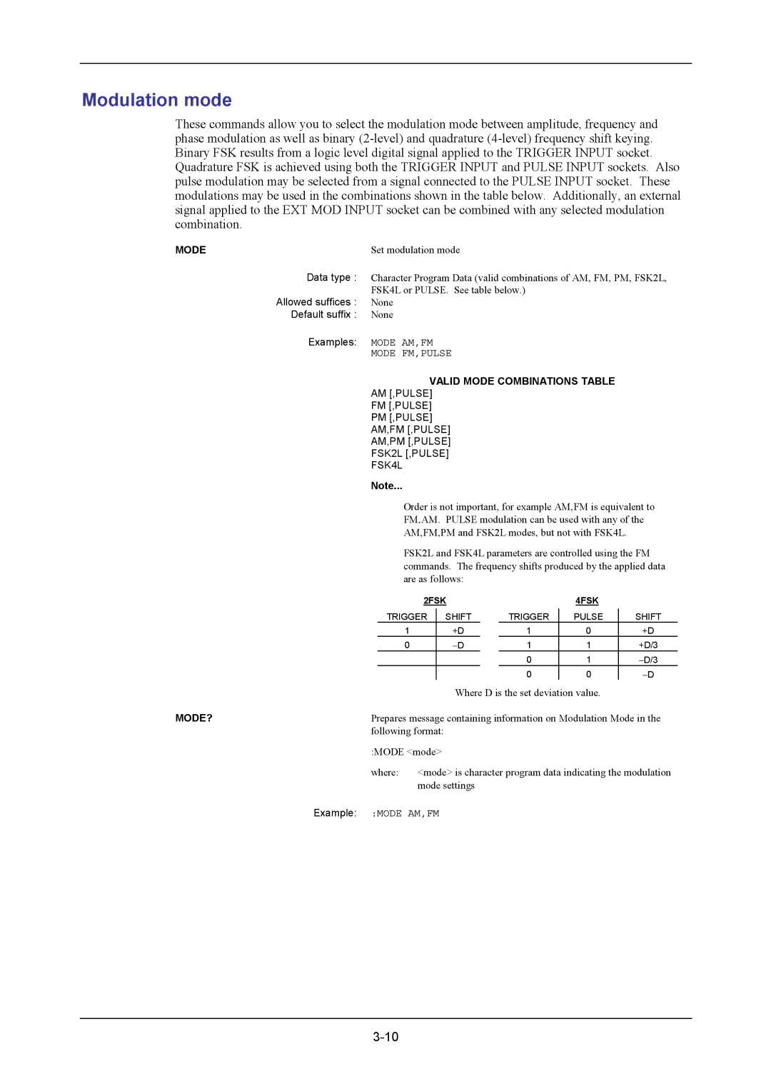
VALID MODE COMBINATIONS TABLE
AM [,PULSE]
FM [,PULSE]
PM [,PULSE]
AM,FM [,PULSE]
AM,PM [,PULSE]
FSK2L [,PULSE]
FSK4L
Note...
Order is not important, for example AM,FM is equivalent to
FM,AM. PULSE modulation can be used with any of the
AM,FM,PM and FSK2L modes, but not with FSK4L.
FSK2L and FSK4L parameters are controlled using the FM commands. The frequency shifts produced by the applied data are as follows:
2FSK |
|
| 4FSK |
| |
TRIGGER | SHIFT |
| TRIGGER | PULSE | SHIFT |
1 | +D |
| 1 | 0 | +D |
0 | −D |
| 1 | 1 | +D/3 |
|
|
| 0 | 1 | −D/3 |
|
| 0 | 0 | −D | |
Where D is the set deviation value.
MODE? | Prepares message containing information on Modulation Mode in the | |
| following format: | |
| :MODE <mode> | |
| where: | <mode> is character program data indicating the modulation |
|
| mode settings |
Example: | :MODE AM,FM | |