SYSTEM CONNECTIONS
Cable locations
To run the cables beneath the flooring effectively, it is necessary to know where the cables enter and exit the printer. The following diagrams show those locations (marked with an X).
All power cords attach to the back of the printer. Listed below are the distances of the printer power cord attachments from the left end of the printer as you face it.
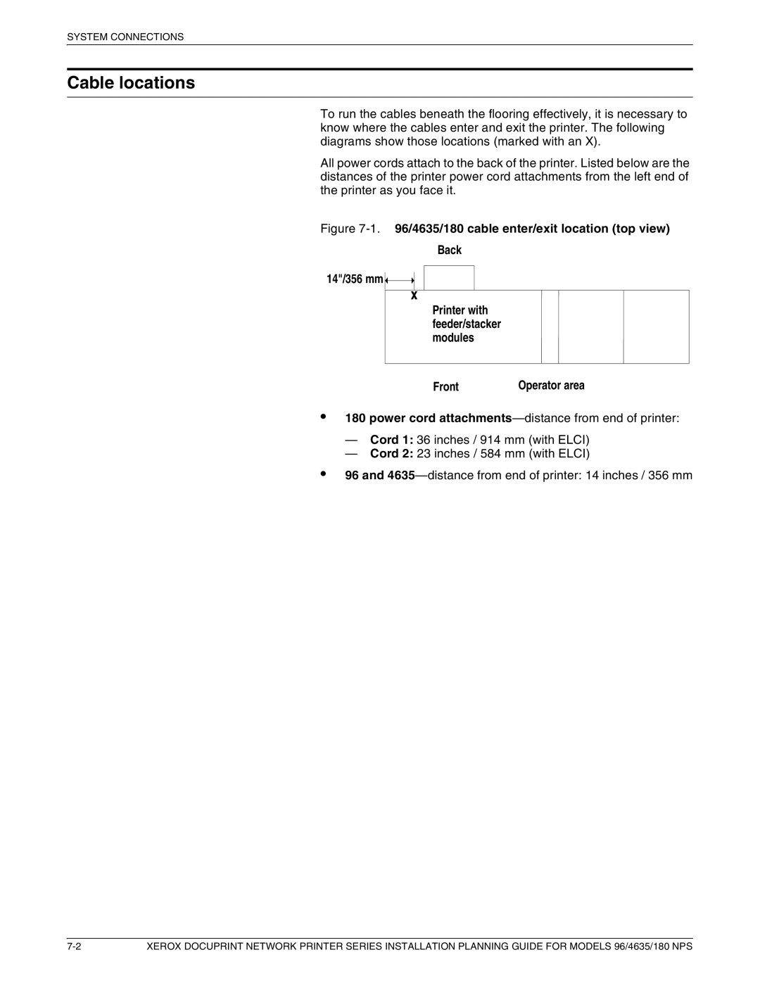
Figure 7-1. 96/4635/180 cable enter/exit location (top view)
Back
14"/356 mm
Printer with feeder/stacker modules
Front | Operator area |
•
•
180 power cord
—Cord 1: 36 inches / 914 mm (with ELCI)
—Cord 2: 23 inches / 584 mm (with ELCI)
96 and
XEROX DOCUPRINT NETWORK PRINTER SERIES INSTALLATION PLANNING GUIDE FOR MODELS 96/4635/180 NPS |