PRINTER SPECIFICATIONS AND REQUIREMENTS
Configuration diagrams with bypass transport
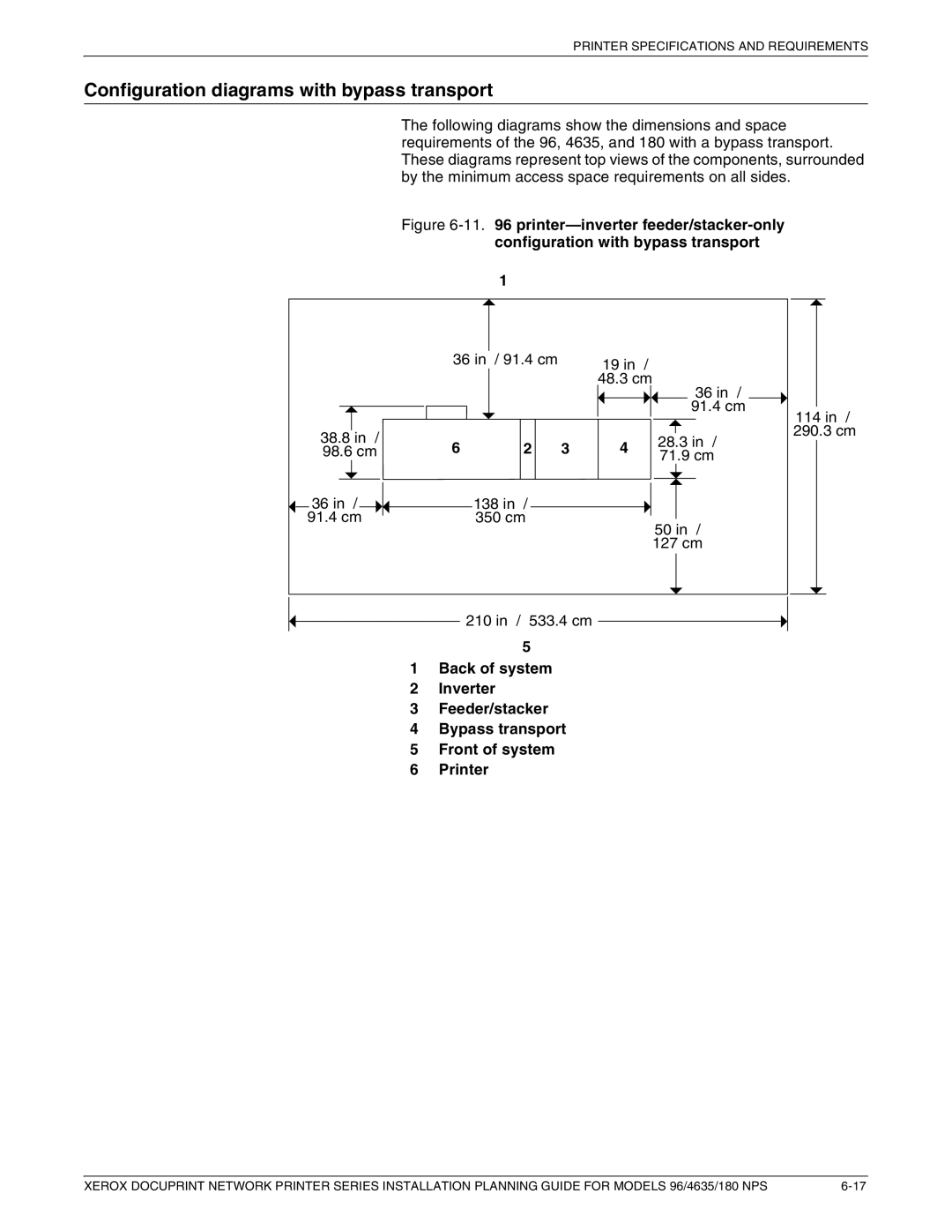
The following diagrams show the dimensions and space requirements of the 96, 4635, and 180 with a bypass transport. These diagrams represent top views of the components, surrounded by the minimum access space requirements on all sides.
Figure 6-11. 96 printer—inverter feeder/stacker-only configuration with bypass transport
1
| 36 in / 91.4 cm | 19 in | / |
|
|
|
|
|
|
|
| |||
|
|
| 48.3 cm | |||||||||||
|
|
|
|
|
|
|
|
|
|
| 36 in / |
|
| |
|
|
|
|
|
|
|
|
|
|
| 91.4 cm |
| 114 in / | |
|
|
|
|
|
|
|
|
|
|
|
|
|
| |
38.8 in / |
|
|
|
|
|
|
|
|
|
|
|
|
| 290.3 cm |
|
|
|
|
|
|
|
|
|
|
| ||||
6 | 2 3 | 4 |
|
|
|
| 28.3 in / | |||||||
98.6 cm |
|
|
|
| 71.9 cm | |||||||||
36 in / |
|
|
|
|
|
|
|
|
|
|
|
|
|
|
|
|
|
|
|
|
|
|
|
|
|
|
|
| |
138 in | / |
|
|
|
|
|
|
|
|
|
|
|
| |
91.4 cm | 350 cm |
|
|
|
|
| 50 in / | |||||||
|
|
|
|
|
|
|
| |||||||
|
|
|
|
|
|
| 127 cm | |||||||
210 in / 533.4 cm
5
1Back of system
2Inverter
3Feeder/stacker
4Bypass transport
5Front of system
6Printer
XEROX DOCUPRINT NETWORK PRINTER SERIES INSTALLATION PLANNING GUIDE FOR MODELS 96/4635/180 NPS |