1
Outline
2. Mechanism
The mechanism of communication is explained in this section to provide an understand- ing of how the robot controller and PLC operate via the
|
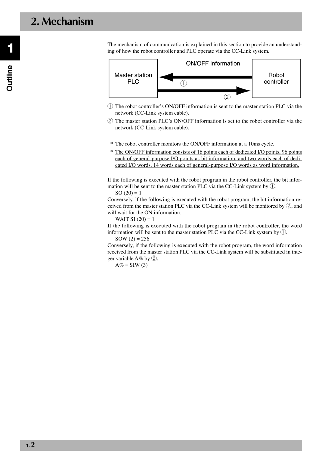
| ON/OFF information |
| |
Master station |
|
|
| Robot |
|
|
| ||
PLC |
| q | controller | |
|
|
|
| |
|
|
|
|
|
|
| w |
| |
|
| |||
qThe robot controller’s ON/OFF information is sent to the master station PLC via the network
wThe master station PLC’s ON/OFF information is set to the robot controller via the network
*The robot controller monitors the ON/OFF information at a 10ms cycle.
*The ON/OFF information consists of 16 points each of dedicated I/O points, 96 points each of
If the following is executed with the robot program in the robot controller, the bit infor- mation will be sent to the master station PLC via the
SO (20) = 1
Conversely, if the following is executed with the robot program, the bit information re- ceived from the master station PLC via the
WAIT SI (20) = 1
If the following is executed with the robot program in the robot controller, the word information will be sent to the master station PLC via the
SOW (2) = 256
Conversely, if the following is executed with the robot program, the word information received from the master station PLC via the
A% = SIW (3)