3
Communication
5. Referring to communication data
The ON/OFF information exchanged with the master station PLC can be referred to using the program- ming unit (hereinafter, MPB).
Note that the MPB display update interval is longer than the
5.1Referring to the data from the programming unit
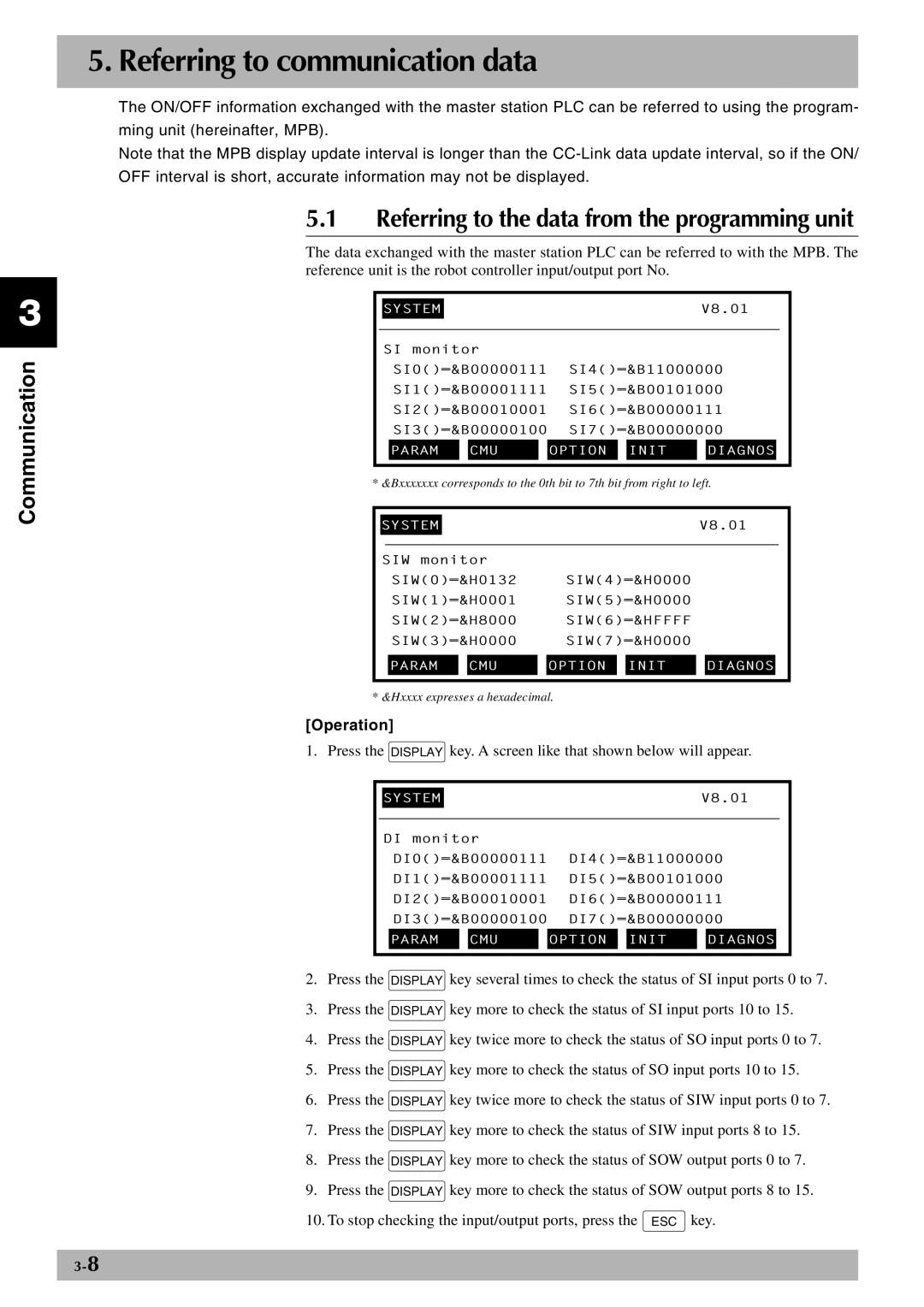
The data exchanged with the master station PLC can be referred to with the MPB. The reference unit is the robot controller input/output port No.
|
|
|
|
|
|
|
|
|
|
|
|
|
|
|
|
| SYSTEM |
|
|
|
|
|
|
| V8.01 | ||||
|
|
|
|
|
|
|
|
|
| |||||
|
| SI monitor |
|
|
|
|
|
|
| |||||
|
|
| SI0()=&B00000111 | SI4()=&B11000000 | ||||||||||
|
|
| SI1()=&B00001111 | SI5()=&B00101000 | ||||||||||
|
|
| SI2()=&B00010001 | SI6()=&B00000111 | ||||||||||
|
|
| SI3()=&B00000100 | SI7()=&B00000000 | ||||||||||
|
|
|
|
|
|
|
|
|
|
|
|
|
| |
|
|
| PARAM |
|
| CMU |
| OPTION |
| INIT |
| DIAGNOS |
|
|
|
|
|
|
|
|
|
|
|
|
|
|
|
|
|
* &Bxxxxxxx corresponds to the 0th bit to 7th bit from right to left.
|
|
|
|
|
|
|
|
|
|
|
|
|
|
|
| SYSTEM |
|
|
|
|
|
| V8.01 | ||||||
|
|
|
|
|
|
|
|
|
|
|
|
|
|
|
| SIW monitor |
|
|
|
|
|
|
|
| |||||
|
|
| SIW(0)=&H0132 |
| SIW(4)=&H0000 |
|
|
|
| |||||
|
|
| SIW(1)=&H0001 |
| SIW(5)=&H0000 |
|
|
|
| |||||
|
|
| SIW(2)=&H8000 |
| SIW(6)=&HFFFF |
|
|
|
| |||||
|
|
| SIW(3)=&H0000 |
| SIW(7)=&H0000 |
|
|
|
| |||||
|
|
|
|
|
|
|
|
|
|
|
|
|
| |
|
|
| PARAM |
| CMU |
| OPTION |
| INIT |
| DIAGNOS |
|
| |
|
|
|
|
|
|
|
|
|
|
|
|
|
|
|
* &Hxxxx expresses a hexadecimal.
[Operation]
1. Press the DISPLAY key. A screen like that shown below will appear.
|
|
|
|
|
|
|
|
|
|
|
|
|
|
|
|
| SYSTEM |
|
|
|
|
|
|
| V8.01 | ||||
|
|
|
|
|
|
|
|
|
| |||||
|
| DI monitor |
|
|
|
|
|
|
| |||||
|
|
| DI0()=&B00000111 | DI4()=&B11000000 | ||||||||||
|
|
| DI1()=&B00001111 | DI5()=&B00101000 | ||||||||||
|
|
| DI2()=&B00010001 | DI6()=&B00000111 | ||||||||||
|
|
| DI3()=&B00000100 | DI7()=&B00000000 | ||||||||||
|
|
| PARAM |
|
| CMU |
| OPTION |
| INIT |
| DIAGNOS |
|
|
|
|
|
|
|
|
|
|
|
|
|
|
|
|
|
2.Press the DISPLAY key several times to check the status of SI input ports 0 to 7.
3.Press the DISPLAY key more to check the status of SI input ports 10 to 15.
4.Press the DISPLAY key twice more to check the status of SO input ports 0 to 7.
5.Press the DISPLAY key more to check the status of SO input ports 10 to 15.
6.Press the DISPLAY key twice more to check the status of SIW input ports 0 to 7.
7.Press the DISPLAY key more to check the status of SIW input ports 8 to 15.
8.Press the DISPLAY key more to check the status of SOW output ports 0 to 7.
9.Press the DISPLAY key more to check the status of SOW output ports 8 to 15.
10. To stop checking the input/output ports, press the ESC key.
