Prestige 201 ISDN Access Router
Chapter 2 Hardware Installation & Initial Setup
This chapter shows you how to make the cable connections to your
Prestige as well as set up your ISDN connection using the SMT.
2.1Front Panel LEDS of P201
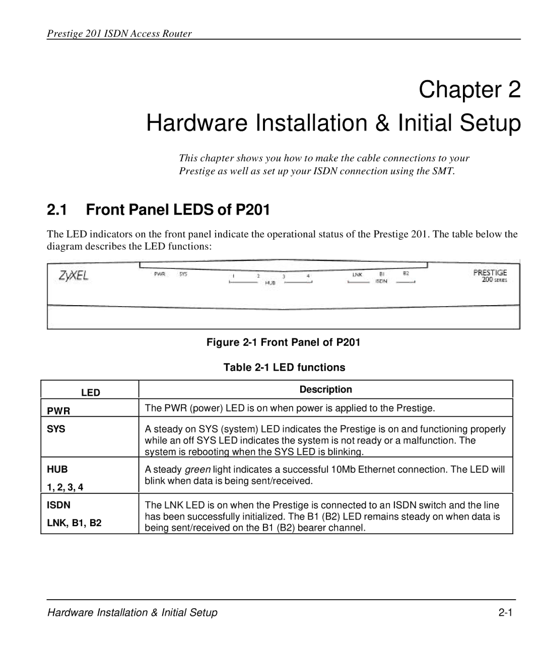
The LED indicators on the front panel indicate the operational status of the Prestige 201. The table below the diagram describes the LED functions:
| Figure | |
| Table | |
|
| |
LED | Description | |
| ||
PWR | The PWR (power) LED is on when power is applied to the Prestige. | |
| ||
SYS | A steady on SYS (system) LED indicates the Prestige is on and functioning properly | |
| while an off SYS LED indicates the system is not ready or a malfunction. The | |
| system is rebooting when the SYS LED is blinking. | |
HUB | A steady green light indicates a successful 10Mb Ethernet connection. The LED will | |
1, 2, 3, 4 | blink when data is being sent/received. | |
| ||
ISDN | The LNK LED is on when the Prestige is connected to an ISDN switch and the line | |
LNK, B1, B2 | has been successfully initialized. The B1 (B2) LED remains steady on when data is | |
being sent/received on the B1 (B2) bearer channel. | ||
|
Hardware Installation & Initial Setup |