OfficeConnect Isdn LAN Modem
95052-8145
3Com Corporation
Bayfront Plaza
Santa Clara, California
Table of Contents
Hardware Description and Installation
Advanced Configuration
Supplementary Voice Call Services
Troubleshooting and Maintenance
Glossary Index 3COM Corporation Limited Warranty
This Guide
How to Use
Shows where to find specific information in this guide
About this Guide
Convention Description
Conventions
List conventions that are used throughout this guide
Icon Description
Applications
Access to the Internet
Introduction
Introduction
Access to a Remote Office
Network locally
A Remote Office
Connectivity
Features
Ease of Installation and Use
High Performance
Remote Management
Remote management using the same Web browser interface
Voice Features
Bandwidth Management
Security
Diagnostics
Warranty
Isdn Standards and Interface
Introduction
Functionality Description
Connection Types
An example of a single connection is shown in Figure
LAN
Application Sharing over the LAN
Kbps B2
Location connection to a remote office LAN
Translation
Destination
Call Routing While No Other Calls Are Connected
Call Routing While One Call Is Already Connected
What is Multilink PPP?
What is BACP/BAP?
Understanding Multilink PPP
Allocation
Multilink PPP Configuration Options
Understanding
Dynamic Bandwidth
Understanding VPNs
Pptp
Network
For Windows Dial-Up Networking Users
Isdn LAN Modem
Hardware Description Installation
Package Contents
Before You Install
Front Panel LED Description
Front panel provides the following LEDs
Color Description
Installing the Isdn LAN Modem
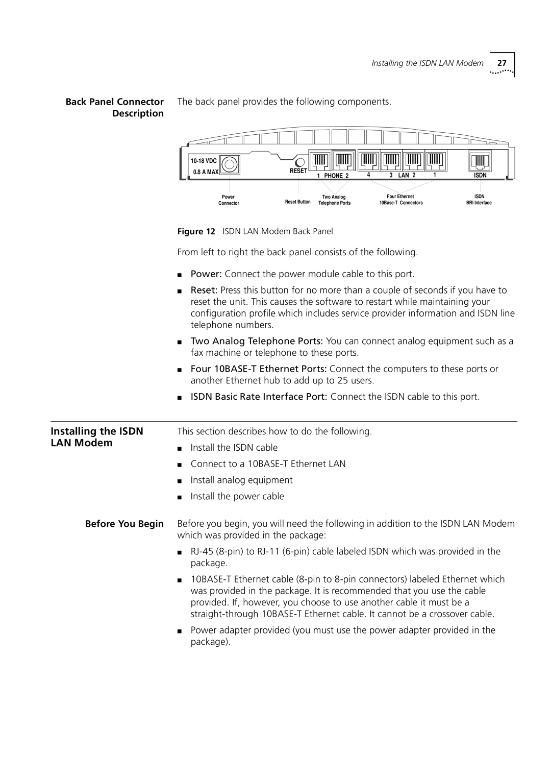
Description
Before You Begin
10BASE-T Ethernet Port
Installing the Isdn Cable To install the Isdn cable
10BASE-T Hub-to-Hub Connection
Common scenario, is as follows
Analog Equipment Connection
Telephone standard, their operation is not guaranteed
Installing the Power To install the power cable
Wall Mounting the Isdn LAN Modem
Cable
Using Stacking Clips
Using Rubber Feet and Stacking Clips
Windows 98
Setting UP TCP/IP for Windows Macintosh
TCP/IP Setup Using
You may be prompted for your installation disks or CD-ROM
Select Network Component Type Dialog Box
TCP/IP Setup Using Windows 98 and Windows 95
Have not already set up TCP/IP, do the following
You will need your Windows NT 4.0 installation CD-ROM
Windows NT
TCP/IP Setup Using Windows NT 4.0
Network Protocols Group Box
TCP/IP Setup Using Mac OS 7.6 or later
Select Unlisted or Update Protocol and then click OK
From the Network group box, click Network Setup
TCP/IP Setup Using Windows 3.11
Setting UP TCP/IP for Windows and Macintosh
Displayed on your computer
Configuring the Isdn LAN Modem
Typical Configuration
Before You Begin
Addresses
For Windows NT 4.0 Users
For Windows 98 and 95 Users
For Windows 3.11 Users
Uncheck Enable Automatic Dhcp Configuration
You are asked to restart your computer Click OK
For Macintosh Users
Click Continue
Configuring the Isdn LAN Modem for the Typical Configuration
Set Password Window
ISP Wizard Window
Click Continue
Click Continue
Isdn LAN Modem WebWizard Main
Main
Isdn LAN Modem Main
Configuring the Isdn LAN Modem
Main configuration page, do the following
Advanced Configuration
Direct Connection to an ISP
When to Select ISP
When to Select Private Network
Setting Up a Connection to the Internet
To an ISP
ISP Service Provider Selection Window
Setting Up Additional Service Providers
Setting Up a Connection to a Remote LAN
Private Network Service Provider Selection Window
Advanced Configuration
Setting Up Additional Service Providers
Provider Profiles
Editing Service
Workstations from
Accessing Service Providers
Configuring Your LAN
Restricting
Local Domain Name
Enable Dhcp Server
Enable NetBIOS Filtering
IP Address and Subnet Mask
Changing Data Call Parameters
Disconnecting an Automatic Data Call
Disconnecting a Manual Data Call
Minimum Call Duration
Call Parameters
Connect Delay
Disconnect Delay
Connect/Disconnect Threshold for the Second B Channel
Default Voice Call Routing Configuration
Protection
Selective Password
Reserving Dhcp
Addresses
OfficeConnect Isdn LAN Modem Isdn Information Sheet
Password
Changing Your
Isdn LAN Modem, do the following
Isdn Parameters Screen
Via an Isdn Modem
Configuring the Isdn LAN Modem from a Remote Location
Configuring the Isdn
LAN Modem Remotely Following
Click TCP/IP Settings
Advanced Configuration
Supplementary Voice Call Services
Supplementary Voice Services
Descriptions of each supplementary voice service follow
Click Isdn Parameters
On port 1 and disabled on port
Call Waiting
Waiting
How Do Do This
Caller ID
Caller ID Date and Time
Go to the Isdn LAN Modem’s main page http//3com.oc.lanmodem
Isdn LAN Modem
Be enabled on your second telephone number as well
To enable or disable Flexible Calling, do the following
Flexible Calling
Order to activate Call Conference
Call Conference
Three-Way Calling
Received or have placed the first call
Call Forwarding
Through the Isdn LAN Modem
Reminder that Call Forwarding is still in effect
Supplementary Voice Call Services
Automatically
PLACING, Receiving Disconnecting Calls
Placing Calls
Placing a Call
Provider
To an Existing Service
Manually
Placing a Call Manually
Calls
Participating in a
Temporary Call
Placing Multilink PPP
Manually
Disconnecting Data
Calls
Automatically
Seconds, a second B channel is added, if not already in use
Idle Timeout
PLACING, Receiving and Disconnecting Calls
Unauthorized opening of the unit will void the warranty
Troubleshooting Maintenance
Monitoring LEDs
Instructions to resolve the problem
LED State Possible Cause Solution
LEDs
B1/B2
Symptoms, Causes, and Solutions Possible Cause
Evaluating Symptoms
Solutions
Solutions
Symptom Possible Cause Solution
For call coming up
To Use two B Channels
Enabled on your Isdn line
Negotiation will not be successful
Contacting Technical
Isdn LAN Modem Resetting the Isdn LAN Modem
Finding More
Information
System Statistics Description
System
Current Call For This Call Information Type Description
Information
Call Information
Isdn Line Information Description
For This Call Last Call Information Type Description
Understanding Last Call Information
Provider Information
Service Provider Information Description
Example of a LAN
Networking Primer
How does a LAN connect to a WAN?
What is a network?
Subnet Mask
What is an IP Address? What is a Subnet Mask?
What is a network?
Appendix a Networking Primer
Configuration and information Web sites
Using the Custom WEB Browser
Browser
Using Favorites
Installing the Custom
Internet Explorer
Isdn LAN Modem Factory C Defaults
Appendix C Isdn LAN Modem Factory Defaults
Refer to for the Isdn LAN Modem specifications
Power
Environmental Operating Range
Year 2000 Compliance
EZ-ISDN 1A
Ordering Isdn Service
This completes the procedure for ordering your Isdn line
Simultaneous Voice Data on the Same Telephone Number
Limitations of Isdn Ordering Codes U EZ-ISDN 1, V
Numbers For Lucent Technologies 5ESS Switches
For Siemens Ewsd Switches
Call Forwarding Variable -- for Call Forwarding
For Nortel DMS-100Switches
Codes for use with the Isdn LAN Modem
Table of Isdn
Ordering Code
Capabilities
Channel to call
Glossary
Kbps Layer
Firmware IP address
Glossary
Glossary
127
Index
UDP
3Com Corporation Limited Warranty
Declaration
Canadian Notice