Powered by Accton
Page
ES4524D Gigabit Ethernet Switch
ES4524D ES4548D F0.0.0.4 E112006-CS-R01 149100030400A
Contents
Setting the System Clock 10-1
Vii
Access Control Lists 15-1
Viii
Vlan Configuration 23-1
Multicast Filtering 28-1
File Management Commands 35-1
Smtp Alert Commands 38-1
Xii
802.1X Port Authentication 43-1
Xiii
Access Control List Commands 44-1
Xiv
Address Table Commands 50-1
Private Vlan Commands 53-1
Xvi
Quality of Service Commands 56-1
Xvii
IPv4 Interface Commands 59-1
Xviii
Xix
Tables
Page
Xxi
Xxii
Xxiii
Figures
Xxiv
Figures IP Filter 12-14 Port Security 13-2
Xxv
Figures
Xxvi
Section I Getting Started
Getting Started
Introduction
Key Features
Key Features
Feature Description
Introduction
Description of Software Features
Description of Software Features
Introduction
Description of Software Features
Password super
System Defaults
System Defaults
Function Parameter Default
Snmp
View defaultview
System Log Status Enabled Messages Logged
System Defaults Function Parameter
Traffic Prioritization Ingress Port Priority Queue Mode
Disabled Igmp Snooping Snooping Enabled
Connecting to the Switch
Initial Configuration
Configuration Options
Remote Connections
Required Connections
Setting Passwords
Basic Configuration
Console Connection
Assigning an IPv4 Address
Setting an IP Address
59-2
Assigning an IPv6 Address
45-1
59-1
60-10
60-4
60-12
60-3
35-2
Obtaining an IPv4 Address
59-3
59-4
60-2
Obtaining an IPv6 Address
60-6
Enabling Snmp Management Access
40-5
40-3
40-14
Managing System Files
40-10
40-11
Saving Configuration Settings
Initial Configuration
Section II Switch Management
Page
Using the Web Interface
Configuring the Switch
Home
Navigating the Web Browser Interface
Action
Web Page Configuration Buttons
Panel Display
Apply Revert Help
IPv6 Neighbor
Switch Main Menu Description
Main Menu
System System Information
12-13
11-1
12-8
15-1
17-1
Lacp
23-5
Class-of-service value
23-1
Current Table
28-4
26-9
28-2
Query Multicast Router
Displaying System Information
Basic System Settings
Field Attributes
System Information
Management Software
Displaying Switch Hardware/Software Versions
CLI Specify the hostname, location and contact information
Main Board
34-8
Switch Information
Displaying Bridge Extension Capabilities
Displaying Bridge Extension Configuration
Command Attributes
Configuring Support for Jumbo Frames
CLI Enter the following command
Command Usage
CLI This example renumbers all units in the stack
Resetting the System
CLI Use the reload command to restart the switch
Renumbering the Stack
Basic System Settings
Setting the Switch’s IP Address IP Version
Setting an IP Address
IPv4 Interface Configuration Manual
Manual Configuration
IPv4 Interface Configuration Dhcp
Using DHCP/BOOTP
Configuring an IPv6 Address
Setting the Switch’s IP Address IP Version 6
IP Address
Setting the Switch’s IP Address IP Version 6
Current Address Table
IPv6 Interface Configuration
60-13
Configuring an IPv6 General Network Prefix
60-14
Protocol Settings
IPv6 General Prefix Configuration
Current Neighbor Cache Table
Adding Static Neighbors IPv6 Neighbor -- Add
60-26
60-22
Managing Firmware
Managing System Files
Copy Firmware
Downloading System Software from a Server
35-7
Deleting Files
Saving or Restoring Configuration Settings
Downloading Configuration Settings for Start-Up
Downloading Configuration Settings from a Server
Console#copy tftp startup-config
Console Port Settings
36-4
36-1
36-2
36-3
Telnet Settings
Configuring the Telnet Interface
Logging Levels
Configuring Event Logging
System Log Configuration
Error resource exhausted
37-5
Remote Log Configuration
37-1
37-2
37-4
37-3
37-7
Displaying Log Messages
Sending Simple Mail Transfer Protocol Alerts
CLI This example shows the event message stored in RAM
Enabling and Configuring Smtp Alerts
38-4
38-1
38-2
38-3
Configuring Sntp
Setting the System Clock
39-2
Setting the Time Zone
39-1
39-3
Snmp Overview
Simple Network Management Protocol
User defined
Enabling the Snmp Agent
SNMPv3 Security Models and Levels
Level Group Read View Write View Notify View Security
CLI The following example enables Snmp on the switch
Setting Community Access Strings
40-2
Specifying Trap Managers and Trap Types
11-5
40-7
Configuring SNMPv3 Management Access
40-8
Setting a Local Engine ID
Specifying a Remote Engine ID
CLI This example sets an SNMPv3 engine ID
CLI This example specifies a remote SNMPv3 engine ID
Configuring SNMPv3 Users
Configuring SNMPv3 Users
40-15
Configuring Remote SNMPv3 Users
Configuring Remote SNMPv3 Users
Configuring SNMPv3 Groups
Authenticated. While all implementations
Topology Change Timer immediately
Any of its configured ports transitions from
That its configuration may have been altered
Supported Notification Messages
40-13
Configuring SNMPv3 Groups
Configuring SNMPv3 Views
Setting SNMPv3 Views
11-17
Simple Network Management Protocol 11-18
Configuring User Accounts
User Authentication
41-1
Configuring Local/Remote Logon Authentication
TACACS+ server
Radius Settings
Global Provides globally applicable Radius settings
Web Telnet
Authentication Server Settings
Tacacs Settings
Configuring Https
Replacing the Default Secure-site Certificate
Address server ip-address
Copy Https Certificate
Configuring the Secure Shell
Authenticating SSH v1.5 Clients
Generating the Host Key Pair
Authenticating SSH v2 Clients
41-21
41-20
41-23
SSH server includes basic settings for authentication
Configuring the SSH Server
41-19
Filtering IP Addresses for Management Access
41-17
41-18
41-25
41-24
Configuring Port Security
42-1
Port Security
Configuring 802.1X Port Authentication
Web Click Security, 802.1X, Information
Displaying 802.1X Global Settings
802.1X protocol provides port authentication
CLI This example shows the default global setting for
43-1
Configuring 802.1X Global Settings
Configuring Port Settings for
CLI This example enables 802.1X globally for the switch
Authorized
802.1X Port Configuration
43-4
43-2
43-5
802.1X Statistics
Displaying 802.1X Statistics
Parameter Description
CLI This example displays the dot1x statistics for port
802.1X Port Statistics
Configuring 802.1X Port Authentication 14-8
Setting an ACL Name and Type
Access Control Lists
Overview
CLI This example creates a standard IP ACL named bill
Configuring a Standard IPv4 ACL
44-2
ACL Configuration Standard IPv4
Configuring an Extended IPv4 ACL
15-4
44-3
ACL Configuration Extended IPv4
Configuring a MAC ACL
44-13
Configuring a Standard IPv6 ACL
44-8
Configuring an Extended IPv6 ACL
15-9
44-9
ACL Configuration Extended IPv6
44-15
Binding a Port to an Access Control List
This switch supports ACLs for ingress filtering only
44-6
Access Control Lists 15-12
Displaying Connection Status
Port Configuration
Field Attributes Web
Current status
Configuration
Field Attributes CLI
Basic information
45-8
CLI This example shows the connection status for Port
Configuring Interface Connections
45-4
45-2
45-6
45-3
Showing Port Statistics
Etherlike Statistics
Port Statistics
Rmon Statistics
Oversize Frames
Formed
Fragments
16-9
45-9
CLI This example shows statistics for port
Creating Trunk Groups
Static Trunk Configuration
Statically Configuring a Trunk
46-2
Setting a Load-Balance Mode for Trunks
Trunk Load Balance Mode
46-3
Enabling Lacp on Selected Ports
46-11
46-4
Lacp Trunk Configuration
Dynamically Creating a Port Channel
Configuring Lacp Parameters
Lacp Aggregation Port
You can display statistics for Lacp protocol messages
Displaying Lacp Port Counters
Lacp Port Counters
Badly formed PDU or an illegal value of Protocol Subtype
Parameter Description Marker Unknown Pkts
Type
Marker Illegal Pkts
Lacp Internal Configuration Information
Displaying Lacp Settings and Status for the Local Side
Field Description
Lacp Port Internal Information
Lacp Neighbor Configuration Information Field Description
Displaying Lacp Settings and Status for the Remote Side
17-14
Broadcast Storm Control
Setting Broadcast Storm Thresholds
45-10
47-1
Configuring Port Mirroring
48-1
Mirror Port Configuration
Command Attribute
Configuring Rate Limits
49-1
Setting Static Addresses
Address Table Settings
50-1
Displaying the Address Table
50-3
Dynamic Addresses
CLI This example sets the aging time to 400 seconds
Changing the Aging Time
50-4
Spanning Tree Algorithm Configuration
For this Region
Region R
Displaying Global Settings
22-4
STA Information
Web Click Spanning Tree, STA, Information
Global settings apply to the entire switch
Configuring Global Settings
Root Device Configuration
Basic Configuration of Global Settings
Configuration Settings for Mstp
Configuration Settings for Rstp
STA Global Configuration
Displaying Interface Settings
22-11
STA Port Information
CLI This example shows the STA attributes for port
Configuring Interface Settings
51-18
22-14
CLI This example sets STA attributes for port
Configuring Multiple Spanning Trees
Mstp Vlan Configuration
51-8
Mstp Port Information
Displaying Interface Settings for Mstp
Configuring Interface Settings for Mstp
51-16
CLI This example sets the Mstp attributes for port
Assigning Ports to VLANs
Vlan Configuration
23-2
Forwarding Tagged/Untagged Frames
CLI This example enables Gvrp for the switch
Enabling or Disabling Gvrp Global Setting
Displaying Basic Vlan Information
Displaying Current VLANs
Command Attributes Web
Max support Vlan numbers 256 Max support Vlan ID 4093
Creating VLANs
Command Attributes CLI
52-17
52-6
Adding Static Members to VLANs Vlan Index
CLI This example creates a new Vlan
52-5
Vlan Static Table Adding Static Members
52-11
Adding Static Members to VLANs Port Index
Configuring Vlan Behavior for Interfaces
Vlan Port Configuration
Configuring Ieee 802.1Q Tunneling
QinQ Tunneling
Layer 2 Flow for Packets Coming into a Tunnel Access Port
Layer 2 Flow for Packets Coming into a Tunnel Uplink Port
General Configuration Guidelines for QinQ
Configuration Limitations for QinQ
52-16
Enabling QinQ Tunneling on the Switch
CLI This example sets the switch to operate in QinQ mode
52-14
Adding an Interface to a QinQ Tunnel
52-15
Tunnel Port Configuration
53-1
Configuring Private VLANs
CLI This example enables private VLANs
Enabling Private VLANs
53-2
Configuring Uplink and Downlink Ports
Configuring Protocol Groups
Configuring Protocol-Based VLANs
Create a protocol group for one or more protocols
54-1
Mapping Protocols to VLANs
54-2
Protocol Vlan Port Configuration
Configuring Protocol-Based VLANs 25-4
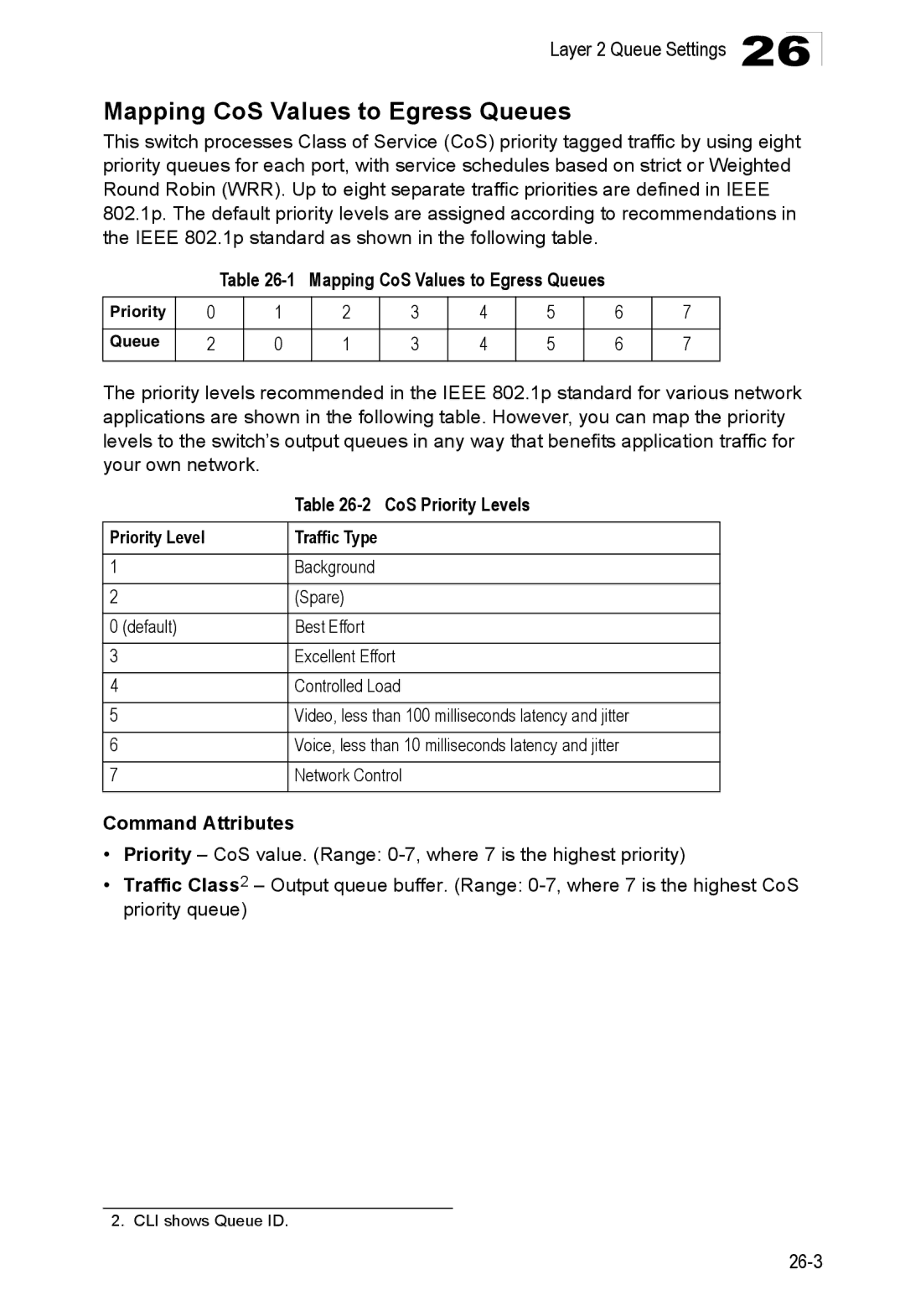
Layer 2 Queue Settings
Class of Service Configuration
Setting the Default Priority for Interfaces
55-3
CLI This example assigns a default priority of 5 to port
Priority Level Traffic Type
Mapping CoS Values to Egress Queues
Mapping CoS Values to Egress Queues
CoS Priority Levels
55-4
Selecting the Queue Mode
55-6
55-2
Setting the Service Weight for Traffic Classes
55-5
Queue Scheduling
55-8
Layer 3/4 Priority Settings
Mapping Layer 3/4 Priorities to CoS Values
Selecting IP Precedence/DSCP Priority
Mapping IP Precedence Priority Level Traffic Type
Mapping IP Precedence
Mapping Dscp Priority IP Dscp Value CoS Value
Mapping Dscp Priority
10, 12, 14 18, 20, 22 26, 28, 30, 32, 34 38, 40
55-13
55-10
IP Port Priority Status
Mapping IP Port Priority
55-11
Configuring Quality of Service Parameters
Quality of Service
Class map is used for matching packets to a specified class
Configuring a Class Map
Class Configuration
Match Class Settings
Configuring Class Maps
56-3
Creating QoS Policies
Policy Map
56-2
Policy Rule Settings Class Settings
Policy Configuration
Policy Options
Configuring Policy Maps
56-6
Attaching a Policy Map to Ingress Queues
56-4
56-5
Quality of Service 27-8
Layer 2 Igmp Snooping and Query
Multicast Filtering
Configuring Igmp Snooping and Query Parameters
57-6
57-1
57-4
57-5
57-9
Displaying Interfaces Attached to a Multicast Router
57-8
Specifying Static Interfaces for a Multicast Router
IP Multicast Registration Table
Displaying Port Members of Multicast Services
Igmp Member Port Table
Assigning Ports to Multicast Services
28-8
Configuring General DNS Service Parameters
Configuring Domain Name Service
58-7
58-3
58-4
58-5
Configuring Static DNS Host to Address Entries
58-6
58-1
DNS Cache
Displaying the DNS Cache
29-6
Cluster Configuration
Switch Clustering
61-1
Cluster Member Configuration
Web Click Cluster, Configuration
Adds Candidate switches to the cluster as Members
61-3
Web Click Cluster, Member Configuration
Displays current cluster Member switch information
Cluster Member Information
61-5
Cluster Candidate Information
Section IIICommand Line Interface
Page
Accessing the CLI
Using the Command Line Interface
Telnet Connection
31-2
Keywords and Arguments
Entering Commands
Command Completion
Getting Help on Commands
Showing Commands
Using Command History
Negating the Effect of Commands
Partial Keyword Lookup
Exec Commands
Understanding Command Modes
General Command Modes
Configuration Commands
Consoleconfig-if# 45-1
Configuration Command Modes Prompt
Keystroke Commands
Command Line Processing
Keystroke Function
Using the Command Line Interface 31-10
Command Group Index Description
CLI Command Groups
55-1
Class of Service
57-1
Enable
General Commands
Example
Disable
Configure
Related Commands
Normal Exec, Privileged Exec
Show history
Syntax Prompt string no prompt
Prompt
End
Exit
This example shows how to quit a CLI session
This command exits the configuration program
Quit
General Commands 33-6
Syntax Hostname name no hostname
System Management Commands
System Management Commands Function Mode
Hostname
Syntax Switch all renumber Default Setting
Switch renumber
Reload
Show ipv6 mtu
Show startup-config
Syntax No jumbo frame Default Setting
Jumbo frame
34-4
Show running-config34-5
Show running-config
Show startup-config34-3
Show system
This command displays system information
Show users
Show version
34-9
System Management Commands 34-10
Managing Firmware
File Management Commands
Saving or Restoring Configuration Settings
Flash/File Commands Function Mode
Copy
35-3
Delete unit filename
This command deletes a file or image
Delete
Syntax
Dir Delete public-key41-20
This command displays a list of files in flash memory
Syntax Dir unit boot-rom config opcode filename
Dir
Column Heading Description
Whichboot
Syntax whichboot unit
File Directory Information
Syntax Boot system unit boot-romconfig opcode filename
Boot system
Dir 35-5 whichboot
File Management Commands 35-8
Syntax Line console vty
Line Commands
Line Commands Function Mode
Line
Syntax Login local no login
Login
No password is specified
Password
Username 41-1 password
Syntax Password 0 7 password no password
Exec-timeout
Timeout login response
Syntax Exec-timeout seconds no exec-timeout
Default value is three attempts
Password-thresh
CLI No timeout Telnet 10 minutes
Syntax Password-thresh threshold no password-thresh
Syntax Databits 7 8 no databits
Silent-time
Databits
Syntax Silent-time seconds no silent-time
Syntax Parity none even odd no parity
Parity
Syntax Stopbits 1
Speed
Stopbits
Syntax Speed bps no speed
Syntax Show line console vty
Disconnect
Show line
Syntax Disconnect session-id
To show all lines, enter this command
Logging on
Event Logging Commands
Event Logging Commands Function Mode
Syntax No logging on Default Setting
Logging history
Flash errors level 3 RAM warnings level 7
Logging history 37-2 logging trap 37-4 clear log
Syntax No logging host hostipaddress
Default Setting Command Mode
Logging host
Logging facility
Logging trap
Disabled Level 7
Syntax Logging trap level no logging trap
Syntax Show logging flash ram sendmail trap
Clear log
Show logging
Syntax Clear log flash ram
Show logging flash/ram display description
Logging facility command
Show logging trap display description
Syntax Show log flash ram
Show log
Following example shows the event message stored in RAM
Event Logging Commands 37-8
38-4
Smtp Alert Commands
Smtp Alert Commands Function Mode
Logging sendmail host
Syntax Logging sendmail source-email email-address
Logging sendmail level
Logging sendmail source-email
Syntax Logging sendmail level level
Syntax No logging sendmail destination-email email-address
Syntax No logging sendmail Default Setting
Logging sendmail destination-email
Logging sendmail
Show logging sendmail
Sntp client
Time Commands
Time Commands Function Mode
Syntax No sntp client Default Setting
Sntp server 39-2 sntp poll 39-3 show sntp
Sntp server
Syntax Sntp server ip1 ip2 ip3
Syntax Sntp poll seconds no sntp poll
Sntp poll
Show sntp
Sntp client 39-1 sntp poll 39-3 show sntp
Clock timezone
Calendar set hour min sec day month year month day year
This command displays the system clock
Calendar set
Show calendar
Time Commands 39-6
Snmp Commands Function Mode
Snmp Commands
Snmp-server
Syntax No snmp-server Default Setting
Show snmp
Snmp-server community
Syntax Snmp-server location text no snmp-server location
Snmp-server contact
Snmp-server location
Syntax Snmp-server contact string no snmp-server contact
Host Address None Notification Type Traps
Snmp-server host
Snmp Version UDP Port
Snmp-server enable traps
Snmp-server enable traps
Issue authentication and link-up-down traps
Snmp-server engine-id
This example shows the default engine ID
This command shows the Snmp engine ID
Show snmp engine-id
This view includes MIB-2
Defaultview includes access to the entire MIB tree
Snmp-server view
Examples
Show snmp view display description
This command shows information on the Snmp views
Show snmp view
Snmp-server group
40-12
Show snmp group display description
Show snmp group
Field Description Groupname Name of an Snmp group
Snmp-server user
Show snmp user
This command shows information on Snmp users
Show snmp user display description
User Access Commands Function Mode
User Authentication Commands
User Account Commands
Authentication Commands Command Group Function
Default Login Settings Username Access-level Password
Enable password
Guest Admin
Authentication login
Authentication Sequence
Authentication Sequence Commands Function Mode
Local
Authentication enable
Tacacs Use Tacacs server password
Username for setting the local user names and passwords
41-8
Radius Client Commands Function Mode
Show radius-server Shows the current Radius settings 41-8
Radius Client
Radius-server port
Default Setting Auth-port
Retransmit Command Mode
Radius-server host
Radius-server retransmit
Radius-server key
Syntax Radius-server key keystring no radius-server key
Show radius-server
Radius-server timeout
Tacacs-server port
TACACS+ Client Commands Function Mode
TACACS+ Client
Tacacs-server host
Show tacacs-server
Tacacs-server key
Syntax Tacacs-server key keystring no tacacs-server key
Ip http port
Web Server Commands
Ip http server
Ip http secure-server
Syntax No ip http secure-server Default Setting
Ip http port
Ip http secure-port41-13copy tftp https-certificate
Ip http secure-port
Portnumber The UDP port used for HTTPS. Range
Telnet Server Commands Function Mode
Telnet Server Commands
Ip telnet server
Sets the SSH server key size 41-19 Copy tftp public-key
Secure Shell Commands
10 Secure Shell Commands Function Mode
Configuration Guidelines
41-16
Ip ssh server
Syntax No ip ssh server Default Setting
Ip ssh crypto host-key generate 41-20 show ssh
Ip ssh timeout
Syntax Ip ssh timeout seconds no ip ssh timeout
Exec-timeout36-4 show ip ssh
Bits
Ip ssh authentication-retries
Ip ssh server-key size
Key-size- The size of server key. Range 512-896 bits
Syntax Ip ssh crypto host-key generate dsa rsa
Delete public-key
Ip ssh crypto host-key generate
Syntax Delete public-key username dsa rsa
Syntax Ip ssh save host-key dsa rsa
Ip ssh crypto zeroize
Ip ssh save host-key
Syntax Ip ssh crypto zeroize dsa rsa
Ip ssh crypto host-key generate
This command displays the current SSH server connections
Show ip ssh
Show ssh
Terminology
Show public-key
Syntax Show public-key user username host
41-25
IP Filter Commands
12 IP Filter Commands Function Mode
Management
Show management
41-26
Max-mac-count
Port Security Commands
Port Security Commands Function Mode
Port security
Shutdown 45-6mac-address-table static
Dot1x system-auth-control
802.1X Port Authentication
802.1X Port Authentication Commands Function Mode
Syntax No dot1x system-auth-control Default Setting
Dot1x port-control
Dot1x default
Default Command Mode
Dot1x max-req
Force-authorized
Dot1x operation-mode
Single-host
Syntax No dot1x re-authentication Command Mode
Dot1x re-authenticate
Dot1x re-authentication
Syntax Dot1x re-authenticate interface
Seconds The number of seconds. Range
Dot1x timeout quiet-period
Dot1x timeout re-authperiod
Dot1x timeout re-authperiod43-5
Statistics Displays dot1x status for each port Interface
Dot1x timeout tx-period
Show dot1x
Syntax Show dot1x statistics interface interface
Backend State Machine
Authenticator State Machine
State- Current state including initialize, reauthenticate
Reauthentication State Machine
IPv4 ACLs
Access Control List Commands
Access Control List Commands Command Groups Function
IPv4 ACL Commands Function Mode
Syntax No permit deny any source bitmask host source
Access-list ip
Syntax No access-list ip standard extended aclname
Permit, deny Ip access-group44-6 show ip access-list44-5
Standard IPv4 ACL
Access-list ip
No permit deny tcp
Extended IPv4 ACL
Permit, deny Ip access-group44-6
Show ip access-list
This command displays the rules for configured IPv4 ACLs
Syntax Show ip access-list standard extended aclname
Show ip access-list44-5
Ip access-group
Show ip access-group
Syntax No ip access-group aclname
IPv6 ACLs
Access-list ipv6
IPv6 ACL Commands Function Mode
Syntax No access-list ipv6 standard extended aclname
Standard IPv6 ACL
Access-list ipv6
New rules are appended to the end of the list
Extended IPv6 ACL
Syntax No permit deny
Any destination-ipv6-address/prefix-length
Next-header next-header dscp dscp flow-label flow-label
This command displays the rules for configured IPv6 ACLs
Show ipv6 access-list
Show ipv6 access-group
Ipv6 access-group
Syntax No ipv6 access-group aclname
MAC ACLs
Access-list mac
MAC ACL Commands Function Mode
Syntax No access-list mac aclname
No permit deny tagged-802.3
Permit, deny MAC ACL
No permit deny tagged-eth2
No permit deny untagged-eth2
This command displays the rules for configured MAC ACLs
Show mac access-list
Syntax Show mac access-list aclname
Show mac access-group
Mac access-group
Syntax Mac access-group aclname
ACL Information
Show access-list
Show access-group
ACL Information Commands Function Mode
44-17
Access Control List Commands 44-18
Port-channel channel-idRange
Interface Commands
Interface Commands Function Mode
Interface
Speed-duplex
Description
Syntax Description string no description
Negotiation
Syntax No negotiation Default Setting
Negotiation 45-3 capabilities
Capabilities
Following example configures port 11 to use autonegotiation
Capabilities 45-4speed-duplex45-2
Negotiation 45-3speed-duplex45-2 flowcontrol
Syntax No flowcontrol Default Setting
Following example enables flow control on port
Flowcontrol
Shutdown
Syntax Media-type mode no media-type
Syntax No shutdown Default Setting
Media-type
Clear counters
Port-channel channel-idRange Default Setting
Syntax Clear counters interface
Shows the status for all interfaces
This command displays the status for an interface
Show interfaces status
Syntax Show interfaces status interface
Shows the counters for all interfaces
This command displays interface statistics
Show interfaces counters
Syntax Show interfaces counters interface
Syntax Show interfaces switchport interface
Show interfaces switchport
Show interfaces switchport display description
Indicates tagged
Indicates membership mode as Trunk or Hybrid
Indicates the default priority for untagged frames
Allowed Vlan
Interface Commands 45-12
Link Aggregation Commands
Link Aggregation Commands
Guidelines for Creating Trunks
Dynamically Creating a Port Channel
Channel-group
Syntax Channel-group channel-idno channel-group
Src-dst-ip
Port channel load-balance
Lacp
Syntax No lacp Default Setting
32768
Lacp system-priority
Lacp admin-keyEthernet Interface
Syntax Lacp admin-key key no lacp admin-key
Lacp admin-key Port Channel
Interface Configuration Port Channel
Lacp port-priority
This command displays Lacp information
Show lacp
LACPDUs Illegal Pkts
Port Channel all
Show lacp counters display description
Type
Show lacp neighbors display description
Show lacp internal display description
Show lacp sysid display description
Show port-channel load-balance
46-12
Enabled for all ports Packet-rate limit 500 pps
Broadcast Storm Control Commands
Switchport broadcast packet-rate
Broadcast Storm Control Commands Function Mode
Broadcast Storm Control Commands 47-2
Port monitor
Mirror Port Commands
Mirror Port Commands Function Mode
Interface Configuration Ethernet, destination port
Syntax Show port monitor interface
This command displays mirror information
Following shows mirroring configured from port 6 to port
Show port monitor
Gigabit Ethernet 1000 Mbps
Rate Limit Commands
Rate Limit Commands Function Mode
Rate-limit
Rate Limit Commands 49-2
Action
Address Table Commands
Address Table Commands Function Mode
Mac-address-table static
Clear mac-address-table dynamic
Mac-address- MAC address Mask Bits to match in the address
Show mac-address-table
Show ipv6 neighbors
Show mac-address-table aging-time
Mac-address-table aging-time
Spanning Tree Commands Function Mode
Spanning Tree Commands
Spanning-tree
Spanning-tree mode
Syntax No spanning-tree Default Setting
Spanning tree is enabled
Spanning-tree forward-time
Spanning-tree forward-time
Spanning-tree forward-time 51-3spanning-tree max-age
Spanning-tree hello-time
Spanning-tree priority
Spanning-tree max-age
Spanning-tree forward-time 51-3spanning-tree hello-time
Long method
Spanning-tree pathcost method
Count The transmission limit in seconds. Range
Spanning-tree mst-configuration
This command limits the maximum transmission rate for BPDUs
Spanning-tree transmission-limit
Mst vlan
MST Configuration
No mst instanceid vlan vlan-range
Syntax Name name
Mst priority
Name
Mst instanceid priority priority no mst instanceid priority
Name
Revision
Syntax Revision number
Number Revision number of the spanning tree. Range
Max-hops
Spanning-tree spanning-disabled
Syntax No spanning-tree spanning-disabled Default Setting
This example disables the spanning tree algorithm for port
Syntax Spanning-tree cost cost no spanning-tree cost
Spanning-tree cost
Priority The priority for a port. Range 0-240, in steps
Syntax No spanning-tree edge-port Default Setting
Spanning-tree port-priority
Spanning-tree edge-port
Spanning-tree portfast
Syntax No spanning-tree portfast Default Setting
Spanning-treeedge-port51-13
Spanning-tree link-type
Spanning-tree mst port-priority51-17
Spanning-tree mst cost
Spanning-tree protocol-migration
Spanning-tree mst port-priority
Syntax Spanning-tree protocol-migration interface
Syntax Show spanning-tree interface mst instanceid
Show spanning-tree
51-19
Show spanning-tree mst configuration
Gvrp and Bridge Extension Commands Function Mode
Vlan Commands
Gvrp and Bridge Extension Commands
Vlan Commands Command Groups Function
Bridge-ext gvrp
Syntax No bridge-ext gvrp Default Setting
Show bridge-ext
Syntax Show gvrp configuration interface
Switchport gvrp
Show gvrp configuration
Syntax No switchport gvrp Default Setting
Garp timer
Editing Vlan Groups
Show garp timer
Syntax Show garp timer interface
Commands for Editing Vlan Groups Function Mode
Show vlan
By default only Vlan 1 exists and is active
Vlan Database Configuration
Vlan
Interface vlan
Configuring Vlan Interfaces
Commands for Configuring Vlan Interfaces Function Mode
Interface vlan
Switchport acceptable-frame-types52-9
Switchport mode
Syntax Switchport mode hybrid trunk no switchport mode
All ports are in hybrid mode with the Pvid set to Vlan
Syntax No switchport ingress-filtering Default Setting
Switchport acceptable-frame-types
Switchport ingress-filtering
Switchport mode
Switchport native vlan
Switchport allowed vlan
No VLANs are included in the forbidden list
Switchport forbidden vlan
52-14
Ieee 802.1Q Tunneling Commands Function Mode
General Configuration Guidelines for QinQ
Dot1q-tunnel
Show dot1q-tunnel52-16 Show interfaces switchport
Syntax No dot1q-tunnel system-tunnel-control Default Setting
0x8100
Switchport dot1q-tunnel tpid
Displaying Vlan Information
Commands for Displaying Vlan Information Function Mode
Syntax Show vlan id vlan-idname vlan-name
This command shows Vlan information
Following example shows how to display information for Vlan
Show vlan
Vlan Commands 52-18
No private VLANs are defined
Private Vlan Commands
Private Vlan Commands Function Mode
Pvlan
Show pvlan
This command displays the configured private Vlan
54-4
Protocol-based Vlan Commands
Protocol-vlan protocol-group Configuring Groups
Protocol-based Vlan Commands Function Mode
No protocol groups are configured
Protocol-vlan protocol-group Configuring
No protocol groups are mapped for any interface
Group-id- Group identifier for a protocol group. Range
This shows protocol group 1 configured for IP over Ethernet
Show protocol-vlan protocol-group
Syntax Show protocol-vlan protocol-group group-id
Mapping for all interfaces is displayed
Show interfaces protocol-vlan protocol-group
Priority Commands Layer Function Mode
Class of Service Commands
Priority Commands Layer
Priority Commands Command Groups Function
Queue bandwidth 55-4 show queue mode
Queue mode
Syntax Queue mode strict wrr no queue mode
Weighted Round Robin
Switchport priority default
Queue cos-mapqueueid cos1 ... cosn no queue cos-map
Queue bandwidth weight1...weight4 no queue bandwidth
Queue bandwidth
Queue cos-map
Show queue cos-map55-6
Show queue mode
Default CoS Priority Levels
This command shows the current queue mode
Syntax Show queue cos-map interface
This command shows the class of service priority map
Show queue bandwidth
Show queue cos-map
Priority Commands Layer 3 Function Mode
Priority Commands Layer 3
Syntax No map ip port Default Setting
Syntax No map ip precedence Default Setting
Following example shows how to map Http traffic to CoS value
List below shows the default priority mapping
Map ip precedence Interface Configuration
Map ip dscp dscp-value cos cos-value no map ip dscp
Syntax No map ip dscp Default Setting
Syntax Show map ip port interface
This command shows the IP port priority map
Show map ip port
Mapping IP Dscp to CoS Values IP Dscp Value
Show map ip precedence
This command shows the IP precedence priority map
Syntax Show map ip precedence interface
Show map ip dscp
This command shows the IP Dscp priority map
Syntax Show map ip dscp interface
55-14
Quality of Service Commands Function Mode
Quality of Service Commands
Syntax No class-map class-map-namematch-any
Class-map
Show class map
Match
Class Map Configuration
No class class-map-name
Policy-map
Class
No policy-mappolicy-map-name
Set
Policy Map Configuration
Drop out-of-profile packets
Policy Map Class Configuration
Police
Syntax No police rate-kbpsburst-byteexceed-action drop set
Syntax No service-policy input policy-map-name
Service-policy
No policy map is attached to an interface
Show policy-mappolicy-map-name class class-map-name
Show class-map
Show policy-map
Syntax Show class-map class-map-name
Show policy-map interface
Port-channel channel-idRange Command Mode
Syntax Show policy-map interface interface input
Quality of Service Commands 56-10
Igmp Snooping Commands
Multicast Filtering Commands
Ip igmp snooping
Ip igmp snooping version
Ip igmp snooping vlan static
Igmp Version
Show mac-address-table multicast
Show ip igmp snooping
Ip igmp snooping querier
Igmp Query Commands
Igmp Query Commands Function Mode
Syntax No ip igmp snooping querier Default Setting
Times
Following shows how to configure the query count to
Ip igmp snooping query-count
Ip igmp snooping query-interval
Ip igmp snooping query-max-response-time
Seconds The report delay advertised in Igmp queries. Range
Ip igmp snooping router-port-expire-time
Switch must use IGMPv2 for this command to take effect
Ip igmp snooping vlan mrouter
Static Multicast Routing Commands
Static Multicast Routing Commands Function Mode
No static multicast router ports are configured
Show ip igmp snooping mrouter
Displays multicast router ports for all configured VLANs
Multicast Filtering Commands 57-10
No ip host name address1 address2 … address8
Domain Name Service Commands
DNS Commands Function Mode
Ip host
Syntax Clear host name
This command deletes entries from the DNS table
Clear host
This example maps two address to a host name
Ip domain-list58-3 ip name-server58-4 ip domain-lookup58-5
Ip domain-name
Ip domain-list
Syntax Ip domain-name name no ip domain-name
Ip domain-name58-3
Ip name-server
Server-address1- IP address of domain-name server
Ip domain-lookup
Syntax No ip domain-lookup Default Setting
Ip domain-name58-3 ip domain-lookup58-5
Ip domain-name58-3 ip name-server58-4
Show hosts
Show dns cache
Show dns
Show dns cache display description
Clear dns cache
This command clears all entries in the DNS cache
IPv4 Configuration Commands Function Mode
IPv4 Interface Commands
Ip address
Ip dhcp restart 59-3 ipv6 address
Ip default-gateway
Syntax Ip default-gateway gateway no ip default-gateway
Gateway IP address of the default gateway
Ip dhcp restart
Following example defines a default gateway for this device
Show ip redirects 59-4 ipv6 default-gateway60-12
This command submits an IPv4 Bootp or Dhcp client request
Show ip redirects
This command displays the settings of an IPv4 interface
Ip default-gateway59-2 Show ipv6 default-gateway60-12
Show ip interface
Interface 45-1 ping ipv6
This command has no default for the host
Ping
Syntax Ping host count countsize size
59 IPv4 Interface Commands 59-6
IPv6 Configuration Commands
IPv6 Interface Commands
Ipv6 address link-local60-9 show ipv6 interface
Ipv6 enable
Syntax No ipv6 enable Default Setting
IPv6 is disabled
No general prefix is defined
Ipv6 general-prefix
Show ipv6 general-prefix60-4
No IPv6 addresses are defined
This command displays all configured IPv6 general prefixes
Show ipv6 general-prefix
Ipv6 address
60-5
Syntax No ipv6 address autoconfig Default Setting
Ipv6 address autoconfig
Ipv6 address Show ipv6 interface
Ipv6 address eui-64
Ipv6 address autoconfig 60-6 show ipv6 interface
Ipv6 address link-local
Show ipv6 interface
Ipv6 enable Show ipv6 interface
Show ipv6 interface display description Field
Maximum transmission unit for this interface
Show ipv6 interface display description
FF022, and solicited nodes FF021FFXXXXXX as described below
Appending those bits to the prefix
Show ipv6 default-gateway
Ipv6 default-gateway
Syntax Ipv6 default-gateway ipv6-addressno ipv6 address
Syntax Ipv6 mtu size no ipv6 mtu
Ipv6 mtu
Show ipv6 mtu display description
Show ipv6 mtu
Show ipv6 traffic
Following example shows the MTU cache for this device
60-15
Ipv6 rcvd Rcvd total
Received in error
Format errors
Errors discovered in processing their IPv6 options, etc
Ipv6 sent
Show ipv6 traffic display description
Prohibited messages received by the interface
Checksum errors
Ipv6 icmp input Input
Input interface for the messages
Ipv6 icmp output
Clear ipv6 traffic
Ping ipv6
Repeat 5 timeout 2 seconds
Ipv6 neighbor
Show ipv6 neighbors 60-26mac-address-table static
Ipv6 nd dad attempts
Syntax Ipv6 nd dad attempts count no ipv6 nd dad attempts
Ipv6 nd ns interval 60-25 show ipv6 neighbors
Milliseconds is used for neighbor discovery operations
Ipv6 nd ns interval
Syntax Show ipv6 neighbors vlan vlan-id ipv6-address
Show ipv6 neighbors
Show ipv6 neighbors display description Field Description
Show ipv6 neighbors display description
Clear ipv6 neighbors
60 IPv6 Interface Commands 60-28
Cluster
Switch Cluster Commands
Switch Cluster Commands Function Mode
Syntax No cluster Default Setting
Syntax Cluster ip-pool ip-addressno cluster ip-pool
Cluster commander
Syntax No cluster commander Default Setting
Cluster ip-pool
No Members
Cluster member
This command shows the switch clustering configuration
Rcommand
Syntax Rcommand id member-id
Member-id- The ID number of the Member switch. Range
Show cluster members
This command shows the current switch cluster members
Show cluster candidates
Switch Cluster Commands 61-6
Section IVAppendices
Appendices
Software Features
Appendix a Software Specifications
Icmp RFC Igmp RFC
Management Features
Groups 1, 2, 3, 9 Statistics, History, Alarm, Event
Standards
Management Information Bases a
Management Information Bases
Software Specifications
Symptom Action
Appendix B Troubleshooting
Problems Accessing the Management Interface
Table B-1 Troubleshooting Chart
Using System Logs
Glossary
Access Control List ACL
See Generic Attribute Registration Protocol
Extended Universal Identifier EUI
Defines frame extensions for Vlan tagging
Ieee 802.1Q
See Port Trunk
IP Precedence
See Ieee
Port Mirroring
TCP/IP protocol commonly used for software downloads
Secure Shell SSH
User Datagram Protocol UDP
Glossary Glossary-8
Numerics
Index
Index-2
Index-3
Index-4
Page
ES4524D ES4548D E112006-CS-R01 149100030400A