Serial Numbers
Page
Contents
Replaceable Parts
Certification
Warranty
Limitation Of Warranty
Exclusive Remedies
Safety Symbols
Printing History
Declaration of Conformity
Page
Page
Page
Introduction
E1445A Arbitrary Function Generator
Safety Considerations
General Information
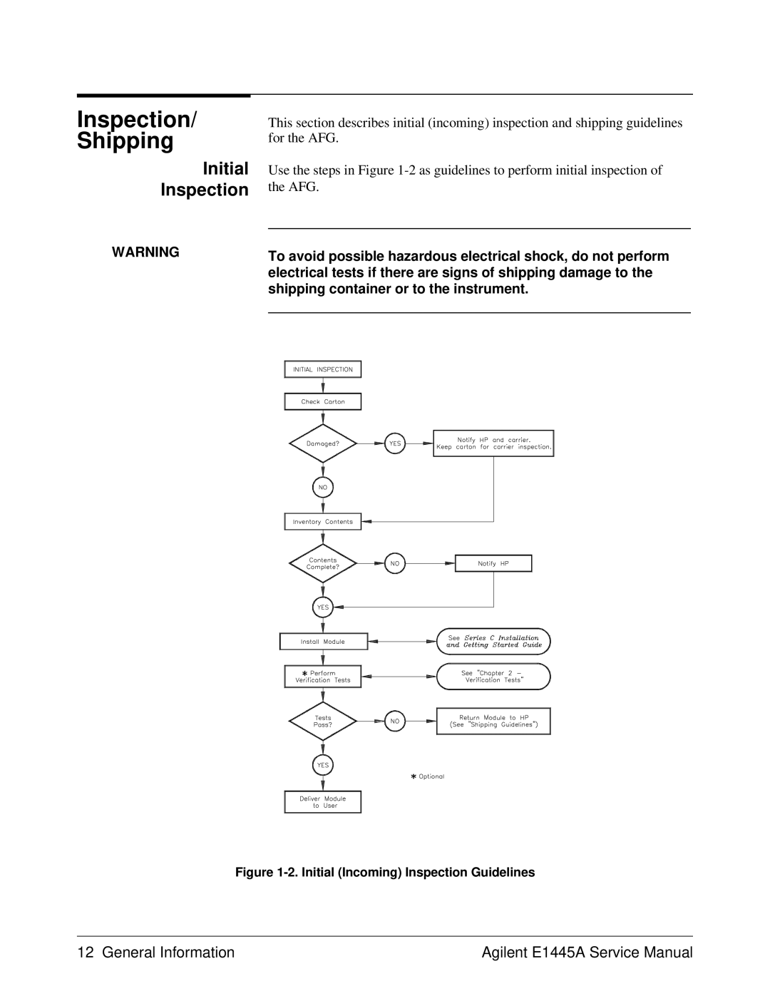
Inspection Shipping
Initial Inspection
Sales and Support Office or Service Center
Shipping
Environment
Specifications
Environment Temperature Humidity
Description
Recommended Test Equipment
Recommended Test Equipment Instrument Requirements Use Model
General Information
Verification Tests
Example programs, these commands would appear as follows
Functional Verification
Execute the AFG self-test
Remove any connections to the AFG front panel Reset the AFG
Functional Verification Self-Test
Verify that the scope shows a 10 MHz squarewave
Set up equipment as shown in Figure
Functional Verification Ref In/Marker Out Test
Start Arm In Test Setup
Functional Verification Start Arm In Test
Functional Verification Start Arm In Test cont’d
Verify that a 1 MHz sinewave appears on the scope
Set up the equipment as shown in Figure
Functional Verification Gate In Test
Functional Verification Gate In Test cont’d
Functional Verification Output Relay Test
Set up the AFG to output a 1 MHz sinewave
Verify that no signal appears on the scope
Purpose of this test is to check the output relay
10! RE-STORE Functest
Functional Verification
On next
Clear Screen
Repeat
Subend
Clear Screen Print SELF-TEST
Clear Screen Print REF IN/MARKER OUT Test
Print Start ARM Test
Print Gate in Test
Print Output Relay Test
Wait
OFF KBD
Disp
Pause
Test # Test Name
Operation Verification
Performance Verification
Test 2-1 DC Zeros
Delete all sequences and segments from memory
Create a user-defined waveform made up of zeros
Set up the AFG to output the waveform defined above
Test 2-1 DC Zeros cont’d
Set the AFG output amplitude
Test 2-1 DC Zeros cont’d
Pause Clear Screen
Print ATTEN,FILTER,AMPLITUDE
Next
Case
END Select
Set up the AFG to output a DC signal
Test 2-2 DC Accuracy
DC Accuracy Test Points Amplitude Filter Test Limits Volts
Test 2-2 DC Accuracy cont’d
This program performs the DC Accuracy test
10! RE-STORE Dclevels
Print FILTER,AMPLITUDE
END
Test 2-3 DC Offset
DC Offset Test Points Amplitude Test Limits Volts
Test 2-3 DC Offset cont’d
If necessary, change the AFG output amplitude
Print AMPLITUDE, Offset
This program performs the DC Offset Test
10! RE-STORE Dcoffset
Disp Voutold=Vout
Set up the AFG to output a 1 kHz sinewave
Test 2-4 AC Accuracy
Test 2-4 AC Accuracy cont’d
This program performs the AC Accuracy Test
10! RE-STORE Aclevels
For I=1 to Select FilterI
Equipment Setup for Test 2-5 and Test
Test 2-5 AC Flatness 250 kHz Filter
Set the AFG output to the reference frequency 1 kHz
Set the AFG output
Error relative to 1 kHz
Frequency Test Limits DB error
Test 2-6 AC Flatness 10 MHz Filter
Set AFG output to the reference frequency 1 kHz
Connect the equipment as shown in Figure
Set up the Power Meter
Test 2-6 AC Flatness 10 MHz Filter cont’d
Test 2-6 AC Flatness 10 MHz Filter cont’d
Frequency Test Limits ±dB error
Test 2-7 Frequency Accuracy
Abort the waveform if it has been previously initiated
Test 2-7 Frequency Accuracy cont’d
Set marker source to Rosc or TRIG, as specified in Table
10! RE-STORE Oscfreq
Add aging rate of ±20 ppm/year
This program performs the Frequency Accuracy Test
Rosc = INT2
Rosc = INT1
Else
END if
Test 2-8 Duty Cycle
Set the AFG to output a square wave
Set AFG output frequency
Test 2-8 Duty Cycle cont’d
Set the AFG frequency range as specified in Table
Duty Cycle Test Points Frequency Test Limits Range Sec
Data MIN,MAX,MIN,MAX
This program performs the Duty Cycle Test
10! RE-STORE Dutycycle
410 !Take readings here Print Output Frequency =FreqI Hz
10. Equipment Setup for Test 2-9 and Test
Test 2-9 Total Harmonic Distortion
Test 2-9 Total Harmonic Distortion cont’d
Where
10 ! RE-STORE Sinethd
This program performs the Total Harmonic Distortion Test
THD Test Points
Output @AfgVOLT &Dbmout$ Set AFG output
Return
Subexit
Print Fundamental
Return Subend
Description Equipment Setup
Test 2-10 Spurious/Non-Harmonic Distortion
Test 2-10 Spurious/Non-Harmonic Distortion cont’d
This program performs the Spurious/Non-harmonic Test
10 ! RE-STORE Nonharm
400 !---------- Perform test For I=1 to
Performance Test Record
Performance Test Test Equipment
Test Accuracy Ratio TAR
11. Performance Test Record for the Agilent E1445A Page 1
11. Performance Test Record for the Agilent E1445A Page 2
11. Performance Test Record for the Agilent E1445A Page 3
TAR
11. Performance Test Record for the Agilent E1445A Page 4
11. Performance Test Record for the Agilent E1445A Page 5
11. Performance Test Record for the Agilent E1445A Page 6
11. Performance Test Record for the Agilent E1445A Page 7
Verification Tests
Calibration Commands
Required Equipment Recommended Environment
Calibration Commands cont’d
CALibrationSECureSTATe mode,code enables
Determine the AFG’s firmware revision
Defeating Calibration Security
Disabling Calibration Security Shown in secured position
DC Adjustment Procedure
DC Adjustment Setup
AFG will return a 1 when ready
DC Adjustment Procedure cont’d
Enable calibration on the AFG
DMM Range Setting for Cal Points 41 Absolute Value DC Offset
DC Calibration Points DMM Settings Changes only
10 ! RE-STORE Dcadjust
Stop
Case =1
Case Else
AC Flatness Adjustment Procedure 250 kHz Filter
Disable calibration security on the AFG
AC Flatness Adjustment Procedure 10 MHz Filter
AC Flatness Adjustment Procedure 10 MHz Filter cont’d
Adjustment Procedure cont’d
10! RE-STORE Acflat
AC Flatness Adjustment Procedure cont’d
250 !RESET Instruments
320 !CLOSE I/O Paths
470 480 !---------- Initialize variables
Printer is CRT
Offsetfactor=Dmmref
PHASEA1,0
LDSTBIND,0
LF,EOI
SET CAL Constant Scale Factors
Print Pass Parameter not Dimensioned Large Enough
Beep
Data 7E6
Check for Valid CAL
Print Gain DAC OUT of Range
Print Turnover DAC OUT of Range
SUB SysterrAddress
Block1=N
SUB Securitycode
Fnend
Skew DAC Adjustment Procedure
Skew DAC Adjustment Setup
Load an initial value of 128 into the delay DAC
Skew DAC Adjustment Procedure cont’d
Set up the AFG to output an 11 dBm, 4 MHz sinewave
Enable calibration security on the AFG
10 ! RE-STORE Skewcal
Print Print CONSTANT, Reading
Set variables for next loop
Check firmware rev
Meas2ndharmSUB Meas2ndharmReading
Adjustments
Replaceable Parts List
Exchange Assemblies
Agilent E1445A Replaceable Parts
Mechanical Parts
Agilent E1445A Code List of Manufacturers
Agilent E1445A Reference Designators
E1445A Replaceable Parts
Service
Equipment Required
Agilent E1445A Tests/Checks
Identifying Problem
Testing the Assembly
Checking for Heat Damage
Removing BNC Connectors
Repair Maintenance Guidelines
Precautions
Service
Page
E1445-90011