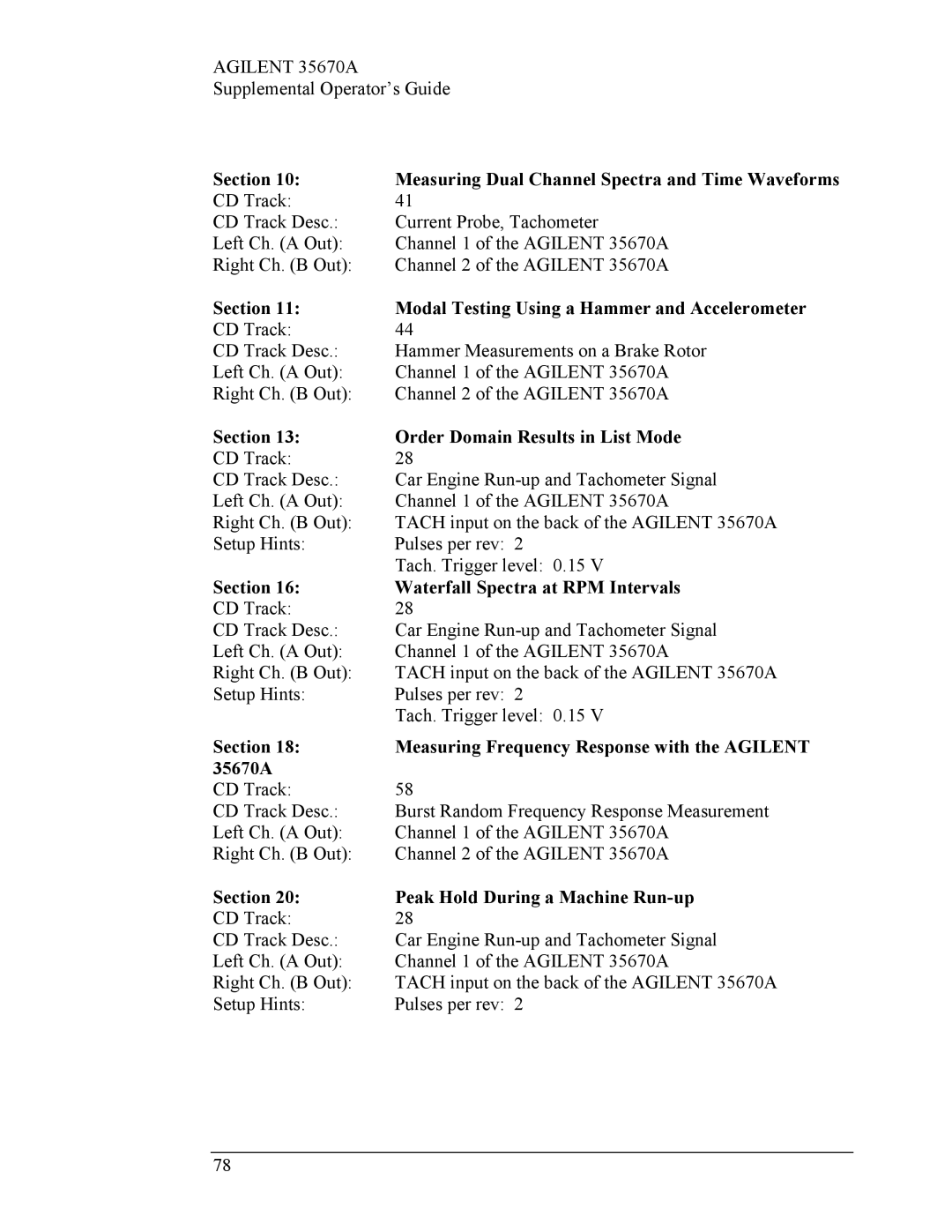
Agilent 35670A specifications
Agilent Technologies Agilent 35670A is a prominent and versatile dynamic signal analyzer designed for various applications in vibration testing, structural analysis, and noise measurement. Engineered to meet the rigorous demands of engineers and researchers, the 35670A is especially valued for its advanced features and functionalities that facilitate detailed analysis and troubleshooting.One of the primary features of the Agilent 35670A is its ability to perform real-time signal analysis. The instrument is equipped with a powerful processing engine that handles large amounts of data efficiently, providing fast and accurate results. This real-time capability is critical for dynamic testing applications, allowing engineers to monitor and analyze signals as they occur, thereby facilitating quicker decision-making and problem identification.
The Agilent 35670A employs advanced Fast Fourier Transform (FFT) algorithms, which provide high-resolution spectral analysis. This feature is essential for engineers needing to identify frequency components in complex signals, making it particularly useful in the fields of acoustics and mechanical engineering. The analyzer supports various types of measurements, such as magnitude and phase, enabling users to delve deeply into their data.
Another key technology embedded in the Agilent 35670A is its ability to perform multi-channel measurements. The instrument can connect to a variety of external sensors and testing devices, making it a flexible choice for users who need to analyze multiple signals simultaneously. This multi-channel feature is particularly advantageous in automotive testing, aerospace applications, and structural health monitoring.
The device also comes equipped with a user-friendly graphical interface, enhancing the overall user experience. The interface facilitates easy navigation and access to various measurement modes, settings, and data visualizations. Additionally, the Agilent 35670A supports automated measurements, allowing users to save time and reduce human error in repetitive testing scenarios.
Furthermore, the Agilent 35670A offers extensive connectivity options, including GPIB and USB interfaces, making it easy to integrate into existing laboratory setups and automated testing systems. This flexibility ensures that users can adapt the analyzer to their specific needs and workflow processes.
In summary, the Agilent 35670A stands out as a sophisticated dynamic signal analyzer that combines advanced signal processing technologies with user-friendly features. Its real-time analysis, multi-channel capabilities, and extensive connectivity options make it an invaluable tool for professionals in various engineering fields, dedicated to achieving precision in their analyses and solutions.
