System Example
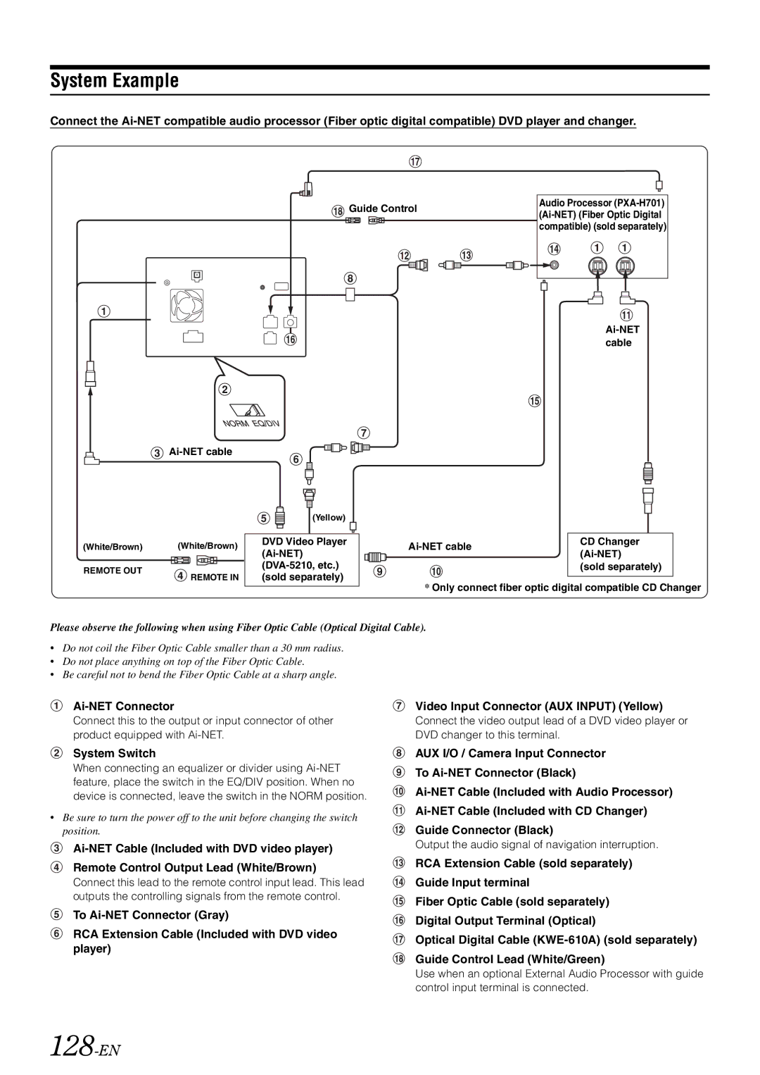
Connect the

![]()
![]() Guide Control
Guide Control
Audio Processor
(White/Brown) (White/Brown)
REMOTE OUT
REMOTE IN
|
|
| (Yellow) |
|
|
|
|
|
|
|
|
|
|
|
|
|
|
| |
|
|
|
|
|
|
|
|
|
|
DVD Video Player |
|
|
| CD Changer | |||||
|
|
| |||||||
|
|
|
| ||||||
|
|
|
| (sold separately) | |||||
(sold separately) |
|
|
|
|
|
| |||
|
|
|
|
|
| ||||
*Only connect fiber optic digital compatible CD Changer
Please observe the following when using Fiber Optic Cable (Optical Digital Cable).
•Do not coil the Fiber Optic Cable smaller than a 30 mm radius.
•Do not place anything on top of the Fiber Optic Cable.
•Be careful not to bend the Fiber Optic Cable at a sharp angle.
Ai-NET Connector
Connect this to the output or input connector of other product equipped with
System Switch
When connecting an equalizer or divider using
•Be sure to turn the power off to the unit before changing the switch position.
Remote Control Output Lead (White/Brown)
Connect this lead to the remote control input lead. This lead outputs the controlling signals from the remote control.
To
RCA Extension Cable (Included with DVD video player)
Video Input Connector (AUX INPUT) (Yellow)
Connect the video output lead of a DVD video player or DVD changer to this terminal.
AUX I/O / Camera Input Connector
To
Output the audio signal of navigation interruption.
RCA Extension Cable (sold separately) Guide Input terminal
Fiber Optic Cable (sold separately)
Digital Output Terminal (Optical)
Optical Digital Cable
Use when an optional External Audio Processor with guide control input terminal is connected.