Black Box Secure Device Servers, 1101 manual Non RS-232 Serial Port Pinouts- LES1102A

Models: 1101 1102 Secure Device Servers

1 164
Download 164 pages 30.63 Kb
Page 16
Image 16

1101 and 1102 Secure Device Servers

Table 3-1. RS-232 DB9 connector pinouts.

Signal

Pin

Definition

CD

1

Received Line Signal Detector

RXD

2

Received Data

TXD

3

Transmitted Data

DTR

4

Data Terminal Ready

GND

5

Signal Ground

DSR

6

Data Set Ready

RTS

7

Request To Send

CTS

8

Clear To Send

RI

9

Ring Indicator

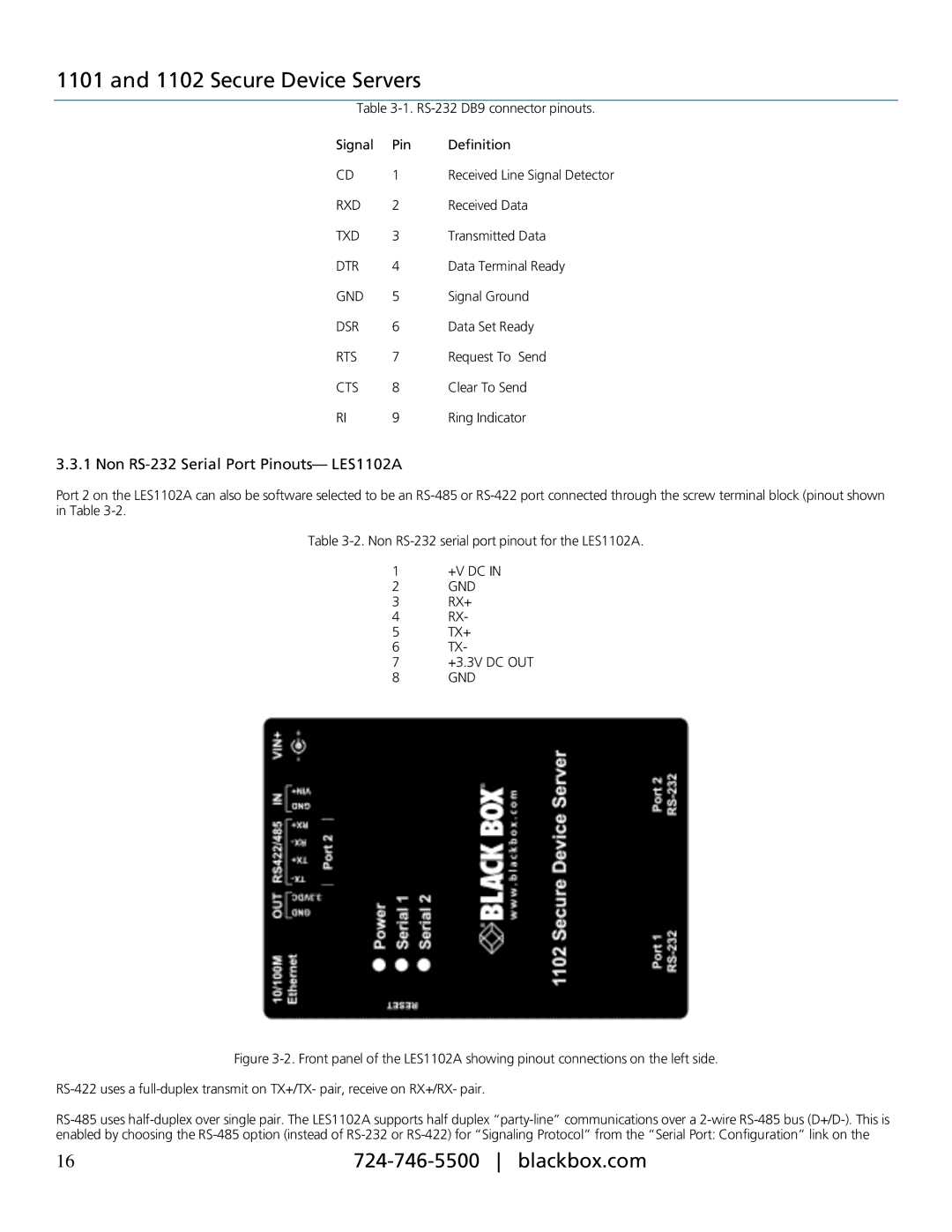
3.3.1 Non RS-232 Serial Port Pinouts— LES1102A

Port 2 on the LES1102A can also be software selected to be an RS-485 or RS-422 port connected through the screw terminal block (pinout shown in Table 3-2.

Table 3-2. Non RS-232 serial port pinout for the LES1102A.

1+V DC IN

2GND

3RX+

4RX-

5TX+

6TX-

7+3.3V DC OUT

8 GND

Figure 3-2. Front panel of the LES1102A showing pinout connections on the left side.

RS-422 uses a full-duplex transmit on TX+/TX- pair, receive on RX+/RX- pair.

RS-485 uses half-duplex over single pair. The LES1102A supports half duplex “party-line” communications over a 2-wire RS-485 bus (D+/D-). This is enabled by choosing the RS-485 option (instead of RS-232 or RS-422) for “Signaling Protocol” from the “Serial Port: Configuration” link on the

16

724-746-5500 blackbox.com

Page 16
Image 16
Black Box Secure Device Servers, 1101 manual Non RS-232 Serial Port Pinouts- LES1102A