USER’S GUIDE
INTERFACE SPECIFICATIONS
Bi-directional Parallel Interface
Interface Connector
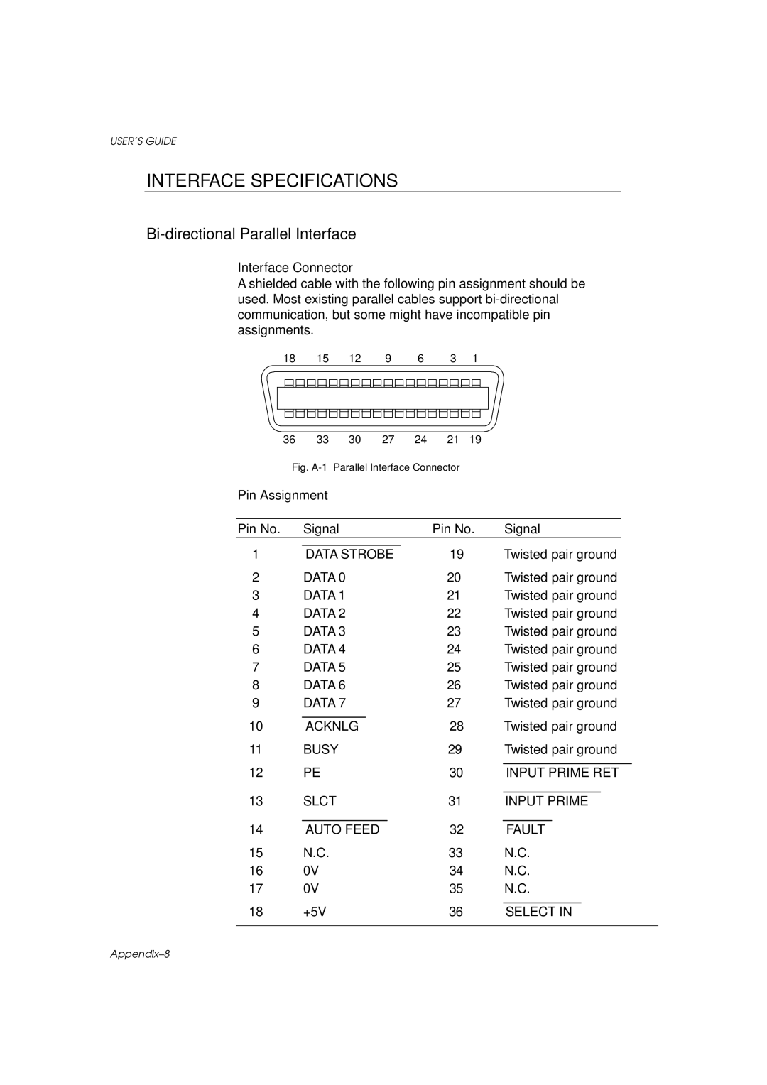
A shielded cable with the following pin assignment should be used. Most existing parallel cables support
18 15 12 9 6 3 1
36 | 33 | 30 | 27 | 24 | 21 | 19 |
|
|
|
|
|
| |
Fig. | Parallel Interface Connector |
|
|
|
|
|
| ||||||
Pin Assignment |
|
|
|
|
|
|
|
|
|
|
|
| |
|
|
|
|
|
|
|
|
|
|
|
| ||
Pin No. | Signal |
|
|
| Pin No. | Signal |
|
| |||||
|
|
|
|
|
|
|
|
|
|
| |||
1 | DATA STROBE |
| 19 |
| Twisted pair ground |
| |||||||
2 | DATA 0 |
|
|
| 20 |
| Twisted pair ground |
| |||||
3 | DATA 1 |
|
|
| 21 |
| Twisted pair ground |
| |||||
4 | DATA 2 |
|
|
| 22 |
| Twisted pair ground |
| |||||
5 | DATA 3 |
|
|
| 23 |
| Twisted pair ground |
| |||||
6 | DATA 4 |
|
|
| 24 |
| Twisted pair ground |
| |||||
7 | DATA 5 |
|
|
| 25 |
| Twisted pair ground |
| |||||
8 | DATA 6 |
|
|
| 26 |
| Twisted pair ground |
| |||||
9 | DATA 7 |
|
|
| 27 |
| Twisted pair ground |
| |||||
|
|
|
|
| 28 |
| Twisted pair ground |
| |||||
10 | ACKNLG |
|
|
|
|
| |||||||
11 | BUSY |
|
|
| 29 |
| Twisted pair ground |
| |||||
|
|
|
|
|
|
|
|
|
|
|
|
| |
12 | PE |
|
|
|
| 30 |
| INPUT PRIME RET |
| ||||
|
|
|
|
|
|
|
|
|
|
|
| ||
13 | SLCT |
|
|
| 31 |
| INPUT PRIME |
| |||||
|
|
|
|
|
|
|
|
|
| ||||
14 | AUTO FEED |
| 32 |
| FAULT |
| |||||||
15 | N.C. |
|
|
|
| 33 |
| N.C. |
| ||||
16 | 0V |
|
|
|
| 34 |
| N.C. |
| ||||
17 | 0V |
|
|
|
| 35 |
| N.C. |
| ||||
|
|
|
|
|
|
|
|
|
|
| |||
18 | +5V |
|
|
|
| 36 |
| SELECT IN |
| ||||
|
|
|
|
|
|
|
|
|
|
|
|
|
|