Performing Hardware Maintenance | Switch Administration |
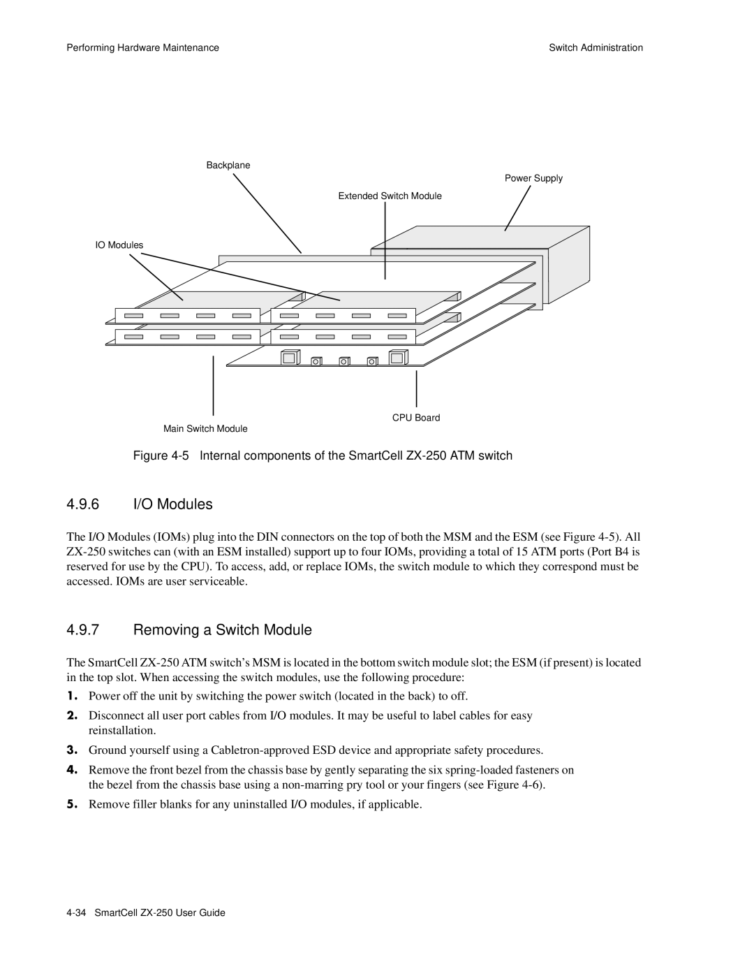
Backplane
Power Supply
Extended Switch Module
IO Modules
CPU Board
Main Switch Module
Figure 4-5 Internal components of the SmartCell ZX-250 ATM switch
4.9.6I/O Modules
The I/O Modules (IOMs) plug into the DIN connectors on the top of both the MSM and the ESM (see Figure
4.9.7Removing a Switch Module
The SmartCell
s• Power off the unit by switching the power switch (located in the back) to off.
¢• Disconnect all user port cables from I/O modules. It may be useful to label cables for easy reinstallation.
••Ground yourself using a
T• Remove the front bezel from the chassis base by gently separating the six
Q• Remove filler blanks for any uninstalled I/O modules, if applicable.