Installation, Start-Up Service Instructions
Make Unit Duct Connections
Instructions on
Roof Curb 48AJ,AK020-030 and 48EJ,EK024-034 Units
Roof Curb 48AJ,AK034-050 and 48EJ,EK038-048 Units
Roof Curb 48AJ,AK060 and 48EJ,EK054-068 Units
Page
Base Unit Dimensions 48AJ,AK020-030
Base Unit Dimensions 48AJ,AK035-050
Base Unit Dimensions 48AJ,AK060
Base Unit Dimensions 48AW,AY020-030
Base Unit Dimensions 48AW,AY035-050
Base Unit Dimensions 48W,AY060
Base Unit Dimensions 48EJ,EK024-034
Base Unit Dimensions 48EJ,EK038-048
Base Unit Dimensions 48EJ,EK054-068
Base Unit Dimensions 48EW,EY024-034
Base Unit Dimensions 48EW,EY038-048
Base Unit Dimensions 48EW,EY054-068
AT Each Corner %
Rigging Weights 48AJ,AK,AW,AY Units
AT Each Corner % 48EJ,EW,EK,EYD024
48EJ,EW,EK,EYD028
48EJ,EW,EK,EYD030
Physical Data 48AJ,AK,AW,AY Units
Unit 48AJ,AK,AW,AY
Quantity Rows...Fins/in
Physical Data 48EJ,EK,EW,EY Units
Unit 48EJ,EK,EW,EY
06D537 06EA250 06EA265
Quantity...Type Ckt 1, Ckt
Operating Weights
Evaporator Fan Motor Data
Air Distribution Thru-the-Bottom
Install Flue Hood
Combustion Fan Housing Location
48A,E Series Staged Gas Implementation
Number of Stages Model Number Position Heat Size Htstgtyp
Stages
Thermistor Designations
Supply-Air Thermistor Connections
Indoor Air Quality Sensor Configuration
Make Electrical Connections
CCN
COM
SIO
DIP
Unbalanced 3-Phase Supply Voltage
Electrical Data 48AJ,AK,AW,AY Units
Min Max
RLA LRA
Qty
30.8/28.0 180.5/177.7 225/225
236.3/230.9
Electrical Data 48EJ,EK,EW,EY Units
Range Exhaust FAN Motor
FLA LRA
MCA Mocp EW,EY
FLA LRA MCA Mocp EW,EY
54.0 23.6 41.6
FLA
NEC
RLA
Field Power Wiring Connections
GND Ground
CCB
Equip
GND
IFC
OFC
Carrier Comfort Network Indoor-Fan Circuit
CCN IFC Pesc
Indoor-Fan Relay Terminal Block
CCN Connection Approved Shielded Cables
Color Code Recommendations
Make Outdoor-Air Inlet Adjustments
Space Temperature Averaging Wiring
Adding Seal Strip to Top of Hood Sides
Adding Seal Strip to Sides of Hood Top Mounting Flange
Mounting Angle With Tabs Attached to Filter Track Assembly
Differential Enthalpy Control and Sensor
Psychrometric Chart for Enthalpy Control
Control Control Point Curve APPROX. DEG
Barometric Relief Damper and Power Exhaust Mounting Details
Unit Size
80.5 79.5 48EJ,EK,EW,EY024-054
120.5 119.5 48EJ,EK,EW,EY058-068
Motormaster III Sensor Location 48EJ,EK,EW,EY054-064
Field Modifications
Side Return Air Conversion
START-UP
Pressure Control Signal VFD SET Point
In. wg
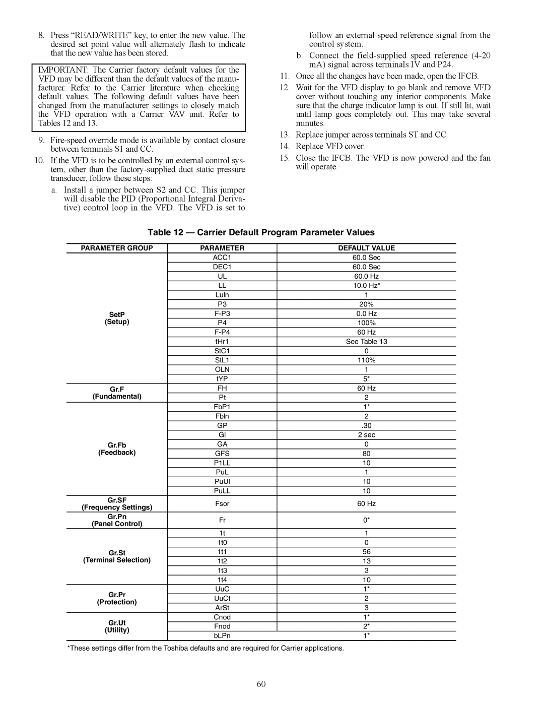
Carrier Default Program Parameter Values
Parameter Group Default Value
Motor Standard Efficiency High Efficiency
Typical Factory Wiring Optional Field Wiring
Building Pressure Signal Level
DIP Switch Configuration
Setting
Open
Closed
DIP Switch Factory Settings
Fan Performance, 48AJ,AK020-030 Vertical Discharge Units
Airflow
Fan Performance, 48AJ,AK035 Vertical Discharge Units
16,000
17,000
18,000
Fan Performance, 48AJ,AK040,050 Vertical Discharge Units
19,000
20,000
17,000 18,000 19,000 20,000
Fan Performance, 48AJ,AK060 Vertical Discharge Units
Fan Performance, 48AW,AY020-030 Horizontal Discharge Units
11,000 12,000 13,000 14,000 15,000
Fan Performance, 48AW,AY035 Horizontal Discharge Units
17,000 18,000
13,000 14,000 15,000 16,000 17,000 18,000
Fan Performance, 48AW,AY040,050 Horizontal Discharge Units
19,000 20,000
16,000 17,000 18,000 19,000 20,000
Fan Performance, 48AW,AY060 Horizontal Discharge Units
26,000 27,000
Fan Performance, 48EJ,EK024,034 Vertical Discharge Units
Fan Performance, 48EJ,EK038,044 Vertical Discharge Units
19,000 20,000 Available External Static Pressure in. wg
Rpm Bhp 000 1066 1096 1125
15,000 16,000 17,000 18,000 19,000 20,000
Fan Performance, 48EJ,EK048 Vertical Discharge Units
Rpm Bhp
000 1086 11.10 1114 11.61 1141 12.14
Fan Performance, 48EJ,EK054-068 Vertical Discharge Units
10,000 949 13.81 970 14.54 990 15.26
Fan Performance, 48EW,EY054-068 Horizontal Discharge Units
26,000 27,000 Available External Static Pressure in. wg
10,000 956 12.99 976 13.66 996 14.32
20,000 21,000 22,000 23,000 24,000 25,000 26,000 27,000
Airflow LOW Speed Medium Speed High Speed
ESP
Motor Limitations
Air Quality Limits
Sequence of Operation
User Defined Set Points
Software Control Link Points
Page
Heat Interlock Relay Wiring
COM Common
Staged Gas System Components
Stage Gas System Inputs/Outputs
Function Location
Input Description
Navigator Display
Navigator Display Menu Structure
Occupied Morning Temperature Software Heat
Version Enabled
DEG. F Reset
Condition
Field-Supplied Smoke Detector Wiring
Smoke Control Modes
Cooling Capacity Staging Table, CV Units with 2 Compressors
Device Pressurization Smoke Purge Evacuation Fire Shutdown
Stages
Service
Typical Gas Heating Section
Lubrication
Manufacturer Lubricant
Evaporator Fan Service and Replacement
Belt Tension Adjustment To adjust belt tension
Evaporator-Fan Motor Replacement
Condenser-Fan Adjustment
Gas Valve Adjustment
Cooling Charging Chart 48EJ,EK,EW,EY024-034
Cooling Charging Chart 48EJ,EK,EW,EY054-068
Protective Devices
Voltage Wire
Indoor Voltage Wire
06D-537 208/230-3-60 Following fan motors have two
20 HP 208/230-3-60
Typical 48EK VAV 24-V Control Circuit
Typical CV 24-V Control Circuit
Typical 48EK VAV 115-V Control Circuit
Typical 48EJ CV 115-V Control Circuit
101
102
Troubleshooting
Typical Refrigerant Circuiting 48AJ,AK,AW,AY027,030
Typical Refrigerant Circuiting 48AJ,AK,AW,AY035
Typical Refrigerant Circuiting 48EJ,EK,EW,EY038,044
Typical Refrigerant Circuiting 48AJ,AK,AW,AY040,050
Typical Refrigerant Circuiting 48EJ,EK,EW,EY048
Typical Refrigerant Circuiting 48EJ,EK,EW,EY054
Typical Refrigerant Circuiting 48AJ,AK,AW,AY060
Typical Refrigerant Circuiting 48EJ,EK,EW,EY064
Typical Refrigerant Circuiting 48EJ,EK,EW,EY068
IGC Control Heating and Cooling
IGC Control Board LED Alarms
Control Board LED Alarms
O Channel Designations Base Module CV
O Channel Designations Base Module VAV
Terminal no Assignment
IAQ
Service Training
START-UP Checklist
General