Chapter 1 Unpacking and Installing the CSS
Installing the CSS 11506
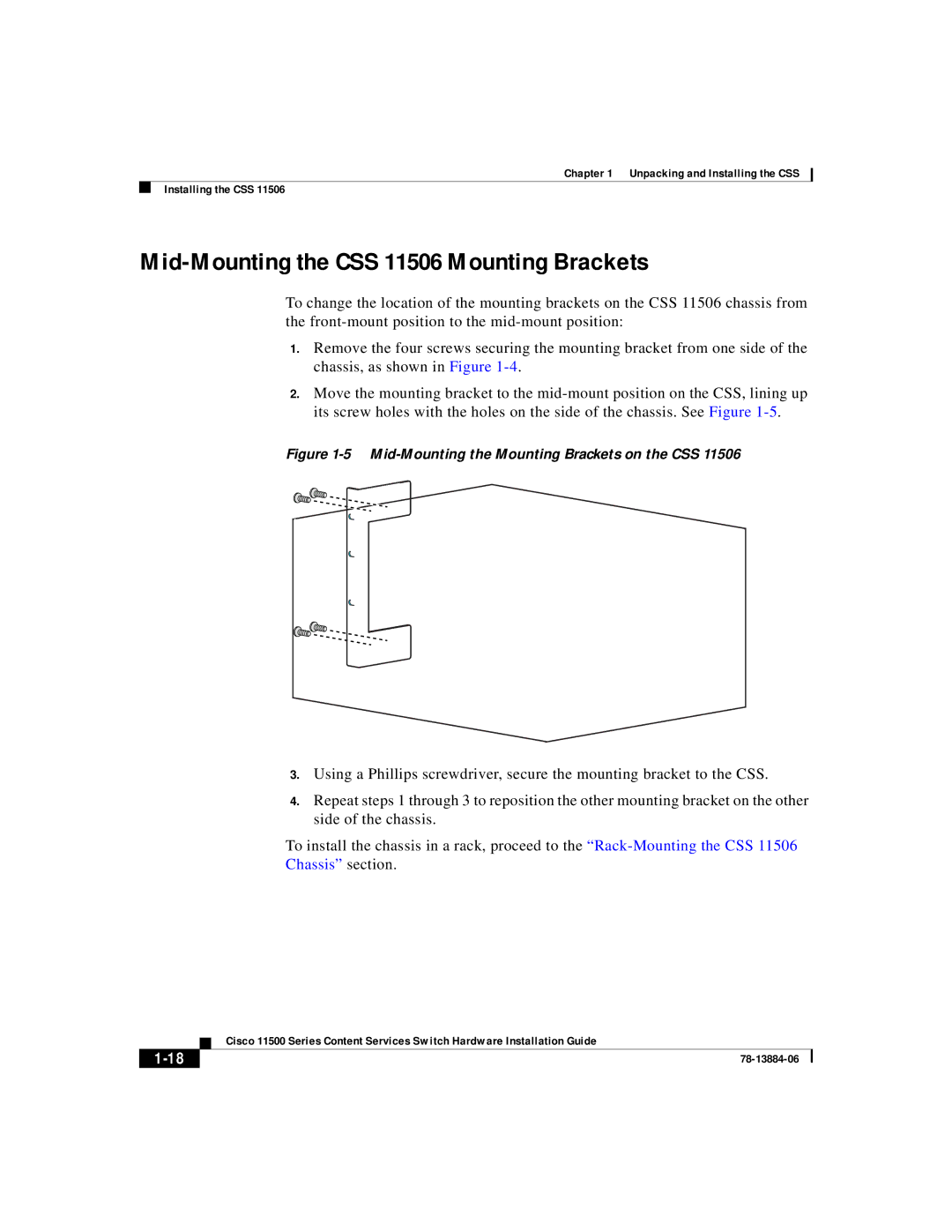
Mid-Mounting the CSS 11506 Mounting Brackets
To change the location of the mounting brackets on the CSS 11506 chassis from the
1.Remove the four screws securing the mounting bracket from one side of the chassis, as shown in Figure
2.Move the mounting bracket to the
Figure 1-5 Mid-Mounting the Mounting Brackets on the CSS 11506
| CAUTION |
| ||
DISCONNECT ALL | ||||
POWER SOURCES | ||||
BEFORE SERVICING | ||||
7 |
| 8 |
| |
1 |
| 2 | 3 | |
4 |
| |||
| 5 | 6 | ||
PS1 | ||||
PS2 | PS3 | |||
|
| |||
|
|
|
|
|
|
|
|
|
|
|
|
|
|
|
|
|
|
|
|
|
|
|
|
|
|
|
|
|
|
|
| ||
|
|
|
|
|
|
|
|
|
|
|
|
|
|
|
|
|
|
|
|
|
|
|
|
|
|
|
|
|
|
|
| ||
| MANAGEMENT |
|
|
|
|
|
|
|
|
|
|
|
|
|
|
|
|
|
|
|
|
|
|
|
|
|
|
|
|
|
|
| |
|
|
|
|
|
|
|
|
|
|
|
|
|
|
|
|
|
|
|
|
|
|
|
|
|
|
| CISCO |
|
|
| |||
STATUS | LINK/ACT | DUPLEX |
|
|
|
|
|
|
|
|
|
|
|
|
|
|
|
|
|
|
|
|
|
|
|
|
|
| 11500 |
| |||
|
| GE 1 | LINK |
| 1 | 2 |
|
|
|
|
|
|
|
|
|
|
|
|
|
|
|
|
|
|
|
|
| CONTENT | SERIES | ||||
|
|
| 3 | 4 |
|
|
|
|
|
|
|
|
|
|
|
|
|
|
|
|
|
|
|
|
|
| SERVICES | SWITCH | |||||
|
|
| GE 2 | LINK |
|
| 5 | 6 | 7 | 8 | 9 | 10 |
|
|
|
|
|
|
|
|
|
|
|
|
|
|
|
|
|
| |||
|
|
|
|
|
|
|
|
|
|
| 11 | 12 |
|
|
|
|
|
|
|
|
|
|
|
|
|
|
|
|
| ||||
|
|
|
|
|
|
|
|
|
|
|
|
|
| 13 | 14 | 15 |
|
|
|
|
|
|
|
|
|
|
|
|
|
| |||
PCMCIA |
|
|
|
|
|
|
|
|
|
|
|
|
|
|
|
|
|
|
|
|
|
|
|
|
|
|
|
| |||||
|
|
|
|
|
|
|
|
|
|
|
|
|
|
|
|
|
|
| 1 | 2 | 3 | 4 | 5 | 6 | 7 |
|
|
|
|
|
|
|
|
|
|
|
|
| CONSOLE |
|
|
|
|
|
|
|
|
|
|
|
|
|
|
|
| 8 | 9 | 10 |
|
|
|
|
| ||||
|
|
|
|
|
|
|
|
|
|
|
|
|
|
|
|
|
|
|
|
|
|
|
| 11 | 12 |
|
|
| |||||
|
|
|
|
|
|
|
|
|
|
|
|
|
|
|
|
|
|
|
|
|
|
|
|
|
|
|
| 13 | 14 | 15 | |||
|
|
|
|
|
|
|
|
|
|
|
|
|
|
|
|
|
|
|
|
|
|
|
|
|
|
|
|
|
|
| |||
STATUS | LINK | DPLX |
GE 1 | LINK |
| 1 |
|
|
|
|
|
| LINK | DPLX |
|
|
|
|
|
|
|
|
|
|
|
|
|
|
|
|
|
|
|
|
| 2 | 3 | 4 |
|
|
|
|
|
|
|
|
|
|
|
|
|
|
|
|
|
|
|
|
|
|
|
|
| |||
| GE 2 | LINK |
|
| 5 | 6 | 7 | 8 |
|
|
|
|
|
|
|
|
|
|
|
|
|
|
|
|
|
|
|
|
| ||
|
|
|
|
|
|
|
|
|
|
| 9 | 10 | 11 | 12 | 13 | 14 |
|
|
|
|
|
|
| LINK | DPLX |
|
|
|
|
| |
|
|
|
|
|
|
|
|
|
|
|
|
|
|
|
| 15 |
|
|
|
|
|
| LINK | DPLX |
|
|
|
|
| ||
|
|
|
|
|
|
|
|
|
|
|
|
|
|
|
|
| 1 | 2 | 3 | 4 | 5 | 6 | 7 |
|
|
|
|
|
|
|
|
|
|
|
|
|
|
|
|
|
|
|
|
|
|
|
|
|
|
|
| 8 | 9 | 10 |
|
|
|
|
| ||||
|
|
|
|
|
|
|
|
|
|
|
|
|
|
|
|
|
|
|
|
|
|
| 11 | 12 |
|
|
| ||||
|
|
|
|
|
|
|
|
|
|
|
|
|
|
|
|
|
|
|
|
|
|
|
|
|
| 13 | 14 | 15 | |||
|
|
|
|
|
|
|
|
|
|
|
|
|
|
|
|
|
|
|
|
|
|
|
|
|
|
|
|
| |||
|
|
|
|
|
|
|
|
|
| LINK | DPLX |
|
|
|
|
|
|
|
|
|
|
|
|
|
|
|
|
|
|
|
|
AC DC |
|
|
|
|
|
|
|
|
| LINK | DPLX |
|
|
|
|
|
|
|
|
|
|
|
|
|
|
|
|
|
|
|
|
|
|
|
|
|
|
|
|
|
|
|
|
|
|
|
|
|
|
|
|
|
|
|
|
|
|
|
|
|
|
| |
OK OK |
|
|
|
|
|
|
|
|
|
|
|
|
|
|
|
|
|
|
|
|
|
|
| LINK | DPLX |
|
|
|
|
| |
|
|
|
|
|
|
|
|
|
|
|
|
|
|
|
|
|
|
|
|
|
|
|
|
|
|
|
|
| |||
|
|
|
|
|
|
|
|
|
|
|
|
|
|
|
|
|
|
|
|
|
|
|
| LINK | DPLX |
|
|
|
|
| |
AC DC
OK OK
AC DC
OK OK
5A |
| ~ |
| ||
| ||
5A |
| ~ |
| ||
| ||
5A |
| ~ |
| ||
| ||
59541
3.Using a Phillips screwdriver, secure the mounting bracket to the CSS.
4.Repeat steps 1 through 3 to reposition the other mounting bracket on the other side of the chassis.
To install the chassis in a rack, proceed to the
| Cisco 11500 Series Content Services Switch Hardware Installation Guide |