Chapter 2 Cabling and Troubleshooting the CSS
Cabling the CSS 11503 and CSS 11506 Modules
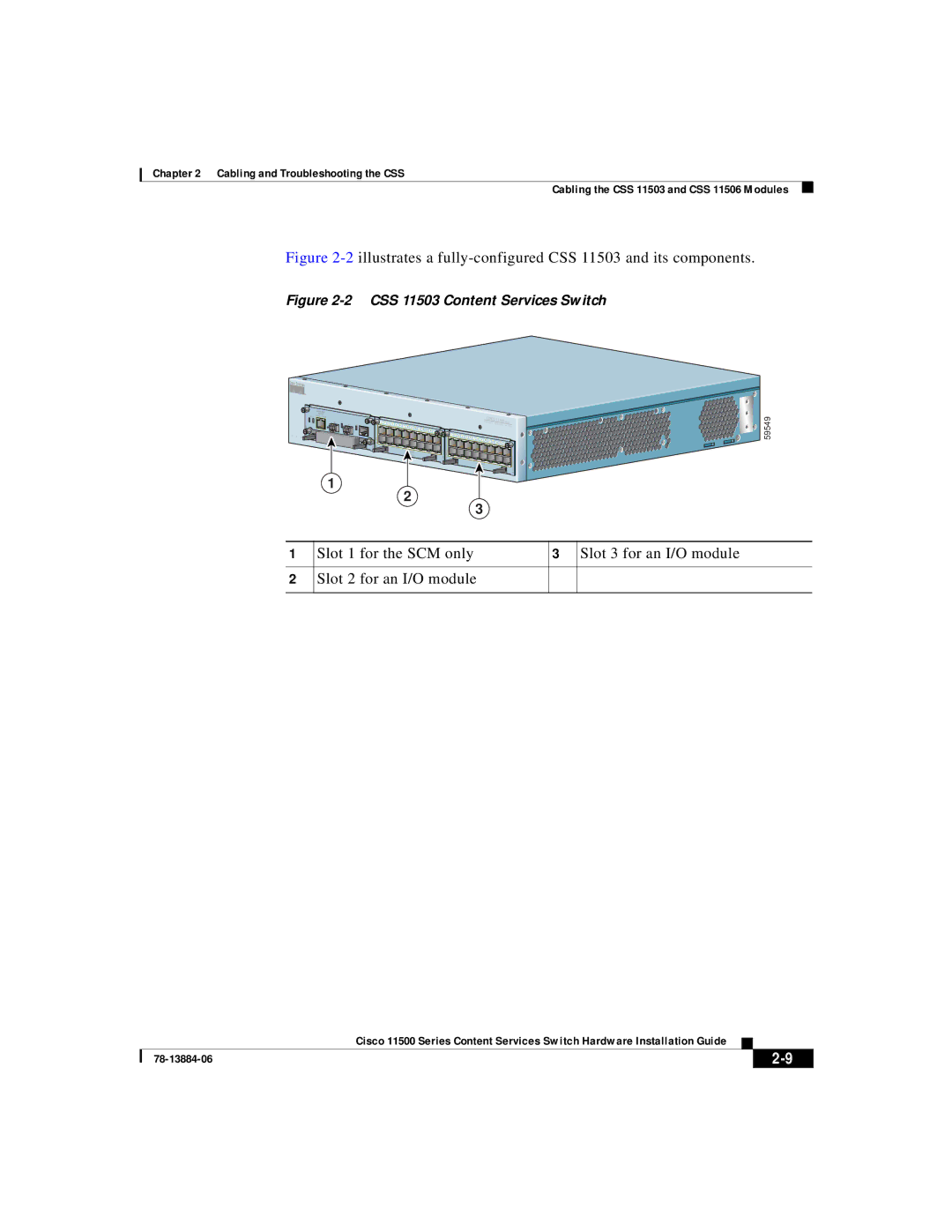
Figure 2-2 illustrates a fully-configured CSS 11503 and its components.
Figure 2-2 CSS 11503 Content Services Switch
|
|
| MANAGEMENT |
|
|
|
|
|
|
|
|
|
|
|
|
|
|
|
|
|
|
|
|
|
|
|
|
|
|
|
|
|
|
| |
|
|
|
|
|
|
|
|
|
|
|
|
|
|
|
|
|
|
|
|
|
|
|
|
|
|
|
|
|
|
|
|
|
| ||
|
| STATUS | LINK/ACT | DUPLEX |
|
|
|
|
|
|
|
|
|
|
|
|
|
|
|
|
|
|
|
|
|
|
|
|
|
| CISCO | 11500 SERIES | |||
|
|
|
|
|
|
|
|
|
|
|
|
|
|
|
|
|
|
|
|
|
|
|
|
|
|
|
|
|
|
| |||||
|
|
|
| GE 1 | LINK |
| 1 | 2 | 3 |
|
|
|
|
|
|
|
|
|
|
|
|
|
|
|
|
|
|
|
| CONT ENT | |||||
|
|
|
|
| GE 2 | LINK |
|
| 4 | 5 | 6 | 7 | 8 | 9 |
|
|
|
|
|
|
|
|
|
|
|
|
|
|
|
|
| SE RV IC ES | S W IT CH | ||
|
|
|
|
|
|
|
|
|
|
|
| 10 | 11 | 12 |
|
|
|
|
|
|
|
|
|
|
|
|
|
|
|
| |||||
|
| PCMCIA |
|
|
|
|
|
|
|
|
|
|
|
|
|
| 13 | 14 | 15 |
|
|
|
|
|
|
|
|
|
|
|
|
|
| ||
1 | 2 | 3 |
|
|
|
|
|
|
|
|
|
|
|
|
|
|
|
|
|
| 1 | 2 | 3 | 4 | 5 | 6 | 7 |
|
|
|
|
|
|
|
|
|
|
|
|
| CONSOLE |
|
|
|
|
|
|
|
|
|
|
|
|
|
|
|
| 8 | 9 | 10 |
|
|
|
|
| ||||||
|
|
|
|
|
|
|
|
|
|
|
|
|
|
|
|
|
|
|
|
|
|
|
|
|
| 11 | 12 | 13 |
|
| |||||
|
|
|
|
|
|
|
|
|
|
|
|
|
|
|
|
|
|
|
|
|
|
|
|
|
|
|
|
|
|
|
|
| 14 | 15 | |
LINK | DPLX |
|
LINK | DPLX |
|
| LINK | DPLX |
| LINK | DPLX |
1
2
3
1 Slot 1 for the SCM only | 3 Slot 3 for an I/O module |
2Slot 2 for an I/O module
59549
|
| Cisco 11500 Series Content Services Switch Hardware Installation Guide |
|
|
|
|
| ||
|
|
| ||
|
|
|