Chapter 1 Unpacking and Installing the CSS
Installing a CSS Module
To install a module:
1.Properly ground yourself prior to handling the module. For example, wear the
2.If the CSS is powered up, power it down.
3.Locate an open slot in the chassis for the module. See Table
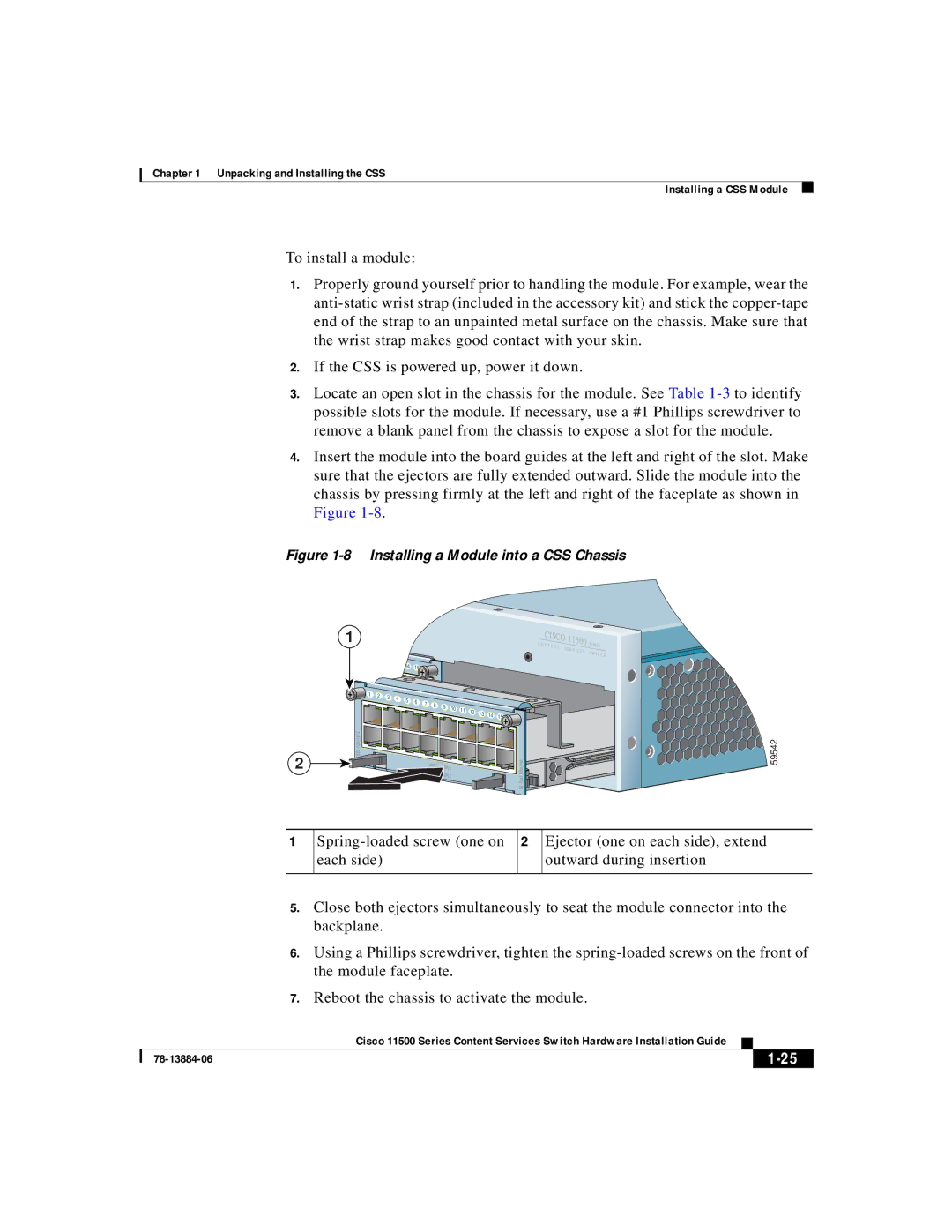
4.Insert the module into the board guides at the left and right of the slot. Make sure that the ejectors are fully extended outward. Slide the module into the chassis by pressing firmly at the left and right of the faceplate as shown in Figure
Figure 1-8 Installing a Module into a CSS Chassis
1 |
|
|
|
|
|
|
|
|
|
|
|
|
| CISCO | 11500 |
| ||
|
|
|
|
|
|
|
|
|
|
|
|
| CON | TENT |
| SERIES | ||
|
|
|
|
|
|
|
|
|
|
|
|
|
|
| SER | |||
|
|
|
|
|
|
|
|
|
|
|
|
|
|
|
|
| VICES | SWI |
10 | 11 |
|
|
|
|
|
|
|
|
|
|
|
|
|
|
|
| TCH |
12 | 13 | 14 |
|
|
|
|
|
|
|
|
|
|
|
|
|
| ||
|
| 15 |
|
|
|
|
|
|
|
|
|
|
|
|
| |||
|
|
|
|
|
|
|
|
|
|
|
|
|
|
|
| |||
|
|
|
|
|
|
|
|
|
|
|
|
|
|
|
|
|
| |
1 | 2 | 3 | 4 | 5 | 6 |
|
|
|
|
|
|
|
|
|
|
|
|
|
|
| 7 | 8 |
|
|
|
|
|
|
|
|
|
|
| ||||
|
|
|
| 9 |
|
|
|
|
|
|
|
|
|
| ||||
|
|
|
|
|
| 10 | 11 | 12 |
|
|
|
|
|
|
| |||
|
|
|
|
|
|
|
|
| 13 | 14 |
|
|
|
|
| |||
|
|
|
|
|
|
|
|
|
|
| 15 |
|
|
|
| |||
|
|
|
|
|
|
|
|
|
|
|
|
|
|
|
| |||
|
|
|
|
|
|
|
|
|
|
|
|
| Ethernet |
|
|
|
| |
2 |
|
|
|
|
|
| LINK | DPLX |
|
|
|
|
|
|
|
| ||
|
|
|
|
|
|
|
|
|
|
|
|
|
|
|
| |||
|
|
|
|
|
|
|
| DPLX |
|
|
|
| Fast |
|
|
|
| |
|
|
|
|
|
|
|
|
|
|
|
|
|
|
|
|
|
| |
|
|
|
|
|
|
|
|
|
|
|
|
|
| 16 |
|
|
|
|
![]()
![]()
![]()
![]()
![]()
![]()
![]()
![]()
![]()
![]()
![]()
![]()
![]()
![]() 59542
59542
1
2
Ejector (one on each side), extend outward during insertion
5.Close both ejectors simultaneously to seat the module connector into the backplane.
6.Using a Phillips screwdriver, tighten the
7.Reboot the chassis to activate the module.
|
| Cisco 11500 Series Content Services Switch Hardware Installation Guide |
|
|
|
|
| ||
|
|
| ||
|
|
|