Chapter 2 Cabling and Troubleshooting the CSS
Connecting the Power Cord
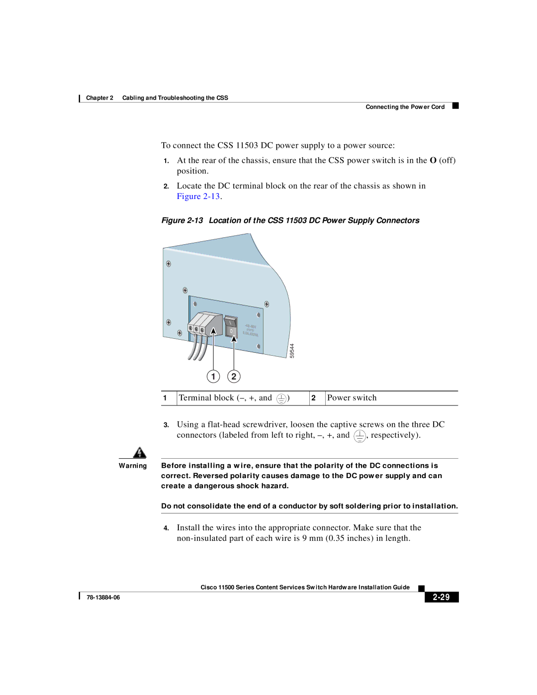
To connect the CSS 11503 DC power supply to a power source:
1.At the rear of the chassis, ensure that the CSS power switch is in the O (off) position.
2.Locate the DC terminal block on the rear of the chassis as shown in Figure
Figure 2-13 Location of the CSS 11503 DC Power Supply Connectors
1
| - |
| |
|
|
| |
| 9. | 0A,430VA |
|
|
|
| |
|
|
| 59544 |
1 | 2 |
|
|
Terminal block | 2 Power switch | ||
3.Using a
connectors (labeled from left to right, |
|
|
|
|
| , respectively). |
|
|
|
|
| ||
|
|
|
|
|
|
|
Warning Before installing a wire, ensure that the polarity of the DC connections is correct. Reversed polarity causes damage to the DC power supply and can create a dangerous shock hazard.
Do not consolidate the end of a conductor by soft soldering prior to installation.
4.Install the wires into the appropriate connector. Make sure that the
|
| Cisco 11500 Series Content Services Switch Hardware Installation Guide |
|
|
|
|
| ||
|
|
| ||
|
|
|