Chapter 2 Cabling and Troubleshooting the CSS
Cabling the CSS 11503 and CSS 11506 Modules
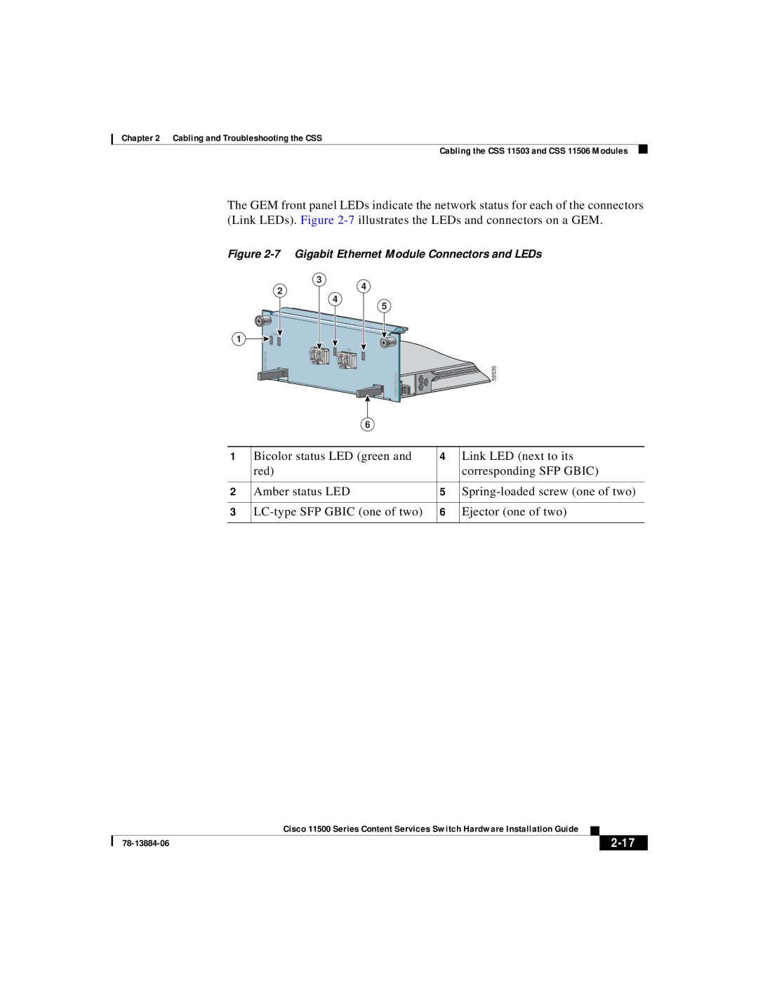
The GEM front panel LEDs indicate the network status for each of the connectors (Link LEDs). Figure
Figure 2-7 Gigabit Ethernet Module Connectors and LEDs
1
C S S 5 - 1 0 M - 2 G E
3
24
4
5
STATUS
GE 1 | LINK |
GE 2 | LINK |
2 Gigabit Ethernet

![]() 59535
59535
6
1 | Bicolor status LED (green and | 4 | Link LED (next to its |
| red) |
| corresponding SFP GBIC) |
|
|
|
|
2 | Amber status LED | 5 | |
|
|
|
|
3 | 6 | Ejector (one of two) | |
|
|
|
|
|
| Cisco 11500 Series Content Services Switch Hardware Installation Guide |
|
|
|
|
| ||
|
|
| ||
|
|
|