Chapter 3 Installing the Cisco ASR 903 Router
Connecting the Cisco ASR 903 Router to the Network
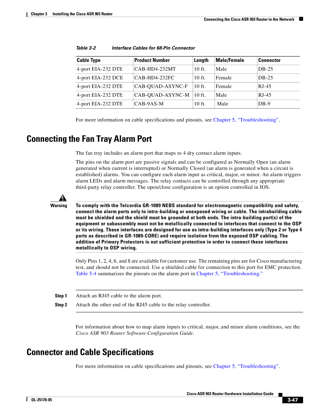
Table | Interface Cables for |
|
| ||
|
|
|
|
|
|
Cable Type |
| Product Number | Length | Male/Female | Connector |
|
|
|
|
| |
10 ft. | Male | ||||
|
|
|
|
| |
10 ft. | Female | ||||
|
|
|
|
| |
10 ft. | Female | ||||
|
|
|
|
| |
10 ft. | Male | ||||
|
|
|
|
| |
| 10 ft. | Male | |||
|
|
|
|
|
|
For more information on cable specifications and pinouts, see Chapter 5, “Troubleshooting”.
Connecting the Fan Tray Alarm Port
The fan tray includes an alarm port that maps to 4 dry contact alarm inputs.
The pins on the alarm port are passive signals and can be configured as Normally Open (an alarm generated when current is interrupted) or Normally Closed (an alarm is generated when a circuit is established) alarms. You can configure each alarm input as critical, major, or minor. An alarm triggers alarm LEDs and alarm messages. The relay contacts can be controlled through any appropriate
Warning To comply with the Telcordia
Only Pins 1, 2, 4, 6, and 8 are available for customer use. The remaining pins are for Cisco manufacturing test, and should not be connected. Use a shielded cable for connection to this port for EMC protection. Table
Step 1 Attach an RJ45 cable to the alarm port.
Step 2 Attach the other end of the RJ45 cable to the relay controller.
For information about how to map alarm inputs to critical, major, and minor alarm conditions, see the Cisco ASR 903 Router Software Configuration Guide.
Connector and Cable Specifications
For more information on cable specifications and pinouts, see Chapter 5, “Troubleshooting”.
|
| Cisco ASR 903 Router Hardware Installation Guide |
|
| |
|
|
| |||
|
|
|
| ||
|
|
|
| ||