Chapter 3 Installing the Cisco ASR 903 Router
Connecting the Cisco ASR 903 Router to the Network
Connecting Cables to SFP Modules
For information on connecting cables to Cisco optical and Ethernet SFP interfaces, see
http://www.cisco.com/en/US/partner/products/hw/modules/ps5455/prod_installation_guides_list.html.
Connecting T1/E1 cables
The physical layer interface for the Cisco ASR 903 Router T1/E1 port is a
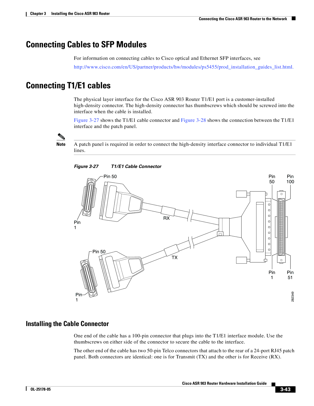
Figure 3-27 shows the T1/E1 cable connector and Figure 3-28 shows the connection between the T1/E1 interface and the patch panel.
Note A patch panel is required in order to connect the
Figure | T1/E1 Cable Connector |
|
|
| Pin 50 | Pin | Pin |
|
| 50 | 100 |
RX
Pin 1
Pin 50
TX
Pin![]() 1
1
Pin | Pin |
1 | 51 |
| 282349 |
Installing the Cable Connector
One end of the cable has a
The other end of the cable has two
|
| Cisco ASR 903 Router Hardware Installation Guide |
|
| |
|
|
| |||
|
|
|
| ||
|
|
|
| ||