Chapter 3 Installing the Cisco ASR 903 Router
Connecting the Cisco ASR 903 Router to the Network
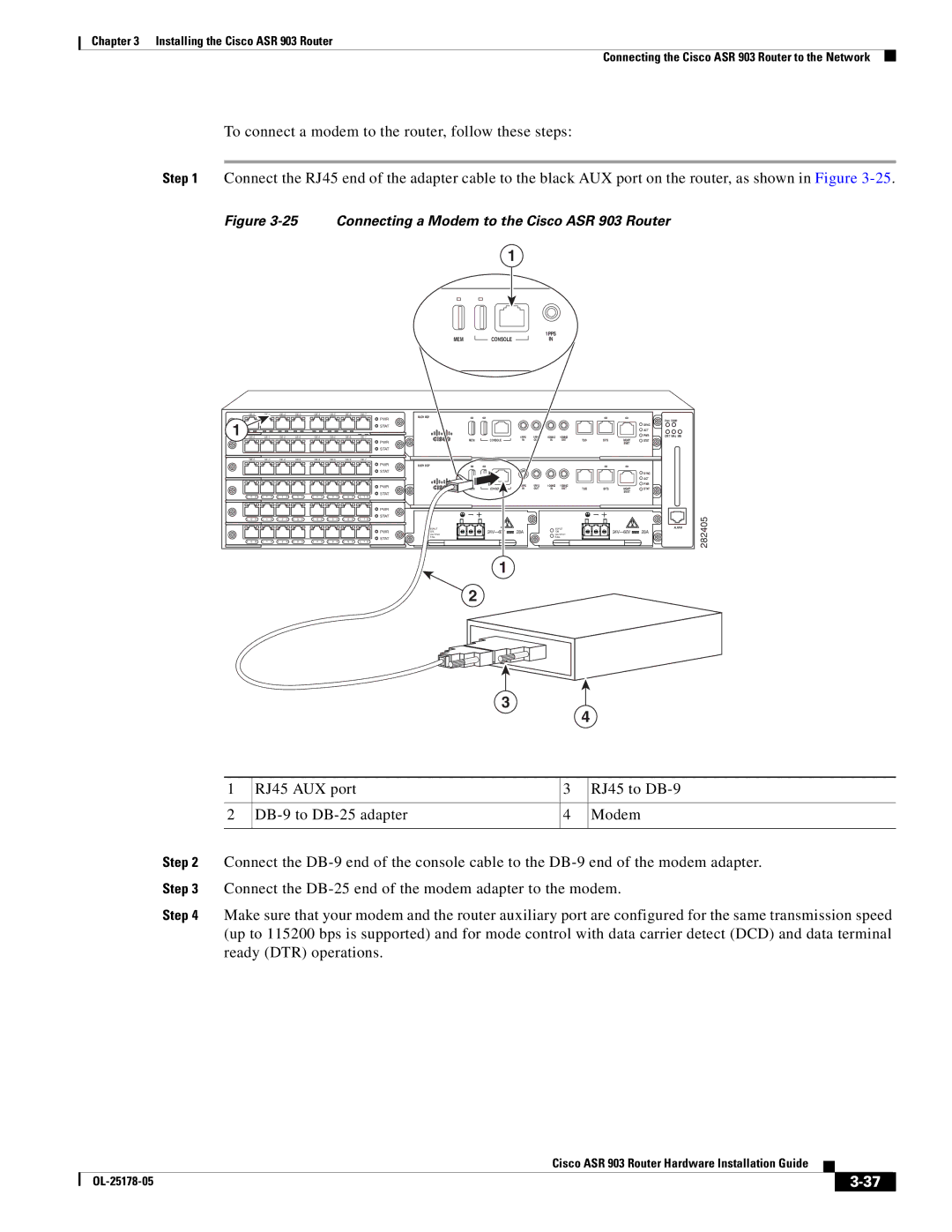
To connect a modem to the router, follow these steps:
Step 1 Connect the RJ45 end of the adapter cable to the black AUX port on the router, as shown in Figure
Figure 3-25 Connecting a Modem to the Cisco ASR 903 Router
1
|
|
|
|
|
| 1PPS |
MEM |
| CONSOLE |
|
| IN | |
|
| |||||
|
|
|
|
|
|
|
| RUDY RSP |
|
|
|
|
|
|
|
|
|
|
| ||||||||
|
|
|
|
|
|
|
| PWR |
|
|
|
|
|
|
|
|
|
|
| |
1 |
|
|
|
|
|
|
|
|
|
|
|
|
|
|
|
|
| FAN TEMP |
| |
|
|
|
|
|
|
| STAT |
|
|
|
|
|
|
|
|
| SYNC |
|
| |
|
|
|
|
|
|
|
|
|
|
|
|
|
|
|
|
| ACT |
|
| |
|
| 1PPS | 1PPS | 1OMHZ | 1OMHZ |
|
|
| PWR | CRIT MAJ MIN |
| |||||||||
|
|
|
|
|
|
|
| PWR | MEM | CONSOLE | IN | OUT | IN | OUT | TOD | BITS | MGMT | STAT |
|
|
|
|
|
|
|
|
|
|
|
|
|
|
|
|
|
| ENET |
|
|
| |
|
|
|
|
|
|
|
| STAT |
|
|
|
|
|
|
|
|
|
|
|
|
|
|
|
|
|
|
|
|
|
|
|
|
| ||||||||
|
|
|
|
|
|
|
| PWR | RUDY RSP |
|
|
|
|
|
|
|
|
|
|
|
|
|
|
|
|
|
|
| STAT |
|
|
|
|
|
|
|
|
| SYNC |
|
|
|
|
|
|
|
|
|
|
|
|
|
|
|
|
|
|
|
| ACT |
|
|
|
|
|
|
|
|
|
| PWR |
|
| 1PPS | 1PPS | 1OMHZ | 1OMHZ |
|
|
| PWR |
|
|
|
|
|
|
|
|
|
| MEM | CONS | TOD | BITS | MGMT | STAT |
|
| |||||
|
|
|
|
|
|
|
|
| IN | OUT | IN | OUT |
|
| ||||||
|
|
|
|
|
|
|
| STAT |
|
|
|
|
|
|
|
| ENET |
|
|
|
|
|
|
|
|
|
|
|
|
|
|
|
|
|
|
|
|
|
|
| |
| L 0 S | L 1 S | L 2 S | L 3 S | L 4 S | L 5 S | L 6 S | L 7 S |
|
|
|
|
|
|
|
|
|
|
|
|
|
|
|
|
|
|
|
| PWR |
|
|
|
|
|
|
|
|
|
|
|
|
|
|
|
|
|
|
|
| STAT |
|
|
|
|
|
|
|
|
|
|
| 2405 |
| L 0 S | L 1 S | L 2 S | L 3 S | L 4 S | L 5 S | L 6 S | L 7 S |
|
|
|
|
|
|
|
|
|
|
| |
|
|
|
|
|
|
|
| PWR | INPUT | 28A |
| INPUT |
|
| 28A | ALARM | ||||
|
|
|
|
|
|
|
| OK |
| OK |
|
|
|
| ||||||
|
|
|
|
|
|
|
|
| OUTPUT |
| OUTPUT |
|
|
| ||||||
|
|
|
|
|
|
|
| STAT | FAIL |
|
|
| FAIL |
|
|
|
|
| ||
|
|
|
|
|
|
|
|
|
|
|
|
|
|
|
|
|
|
| 8 | |
| L 0 S | L 1 S | L 2 S | L 3 S | L 4 S | L 5 S | L 6 S | L 7 S |
|
|
|
|
|
|
|
|
|
|
| |
|
|
|
|
|
|
|
|
|
|
|
|
|
|
|
|
|
|
|
| 2 |
|
|
|
|
|
|
|
|
|
| 1 |
|
|
|
|
|
|
|
|
|
|
|
|
|
|
|
|
|
|
| 2 |
|
|
|
|
|
|
|
|
|
|
|
|
|
|
|
|
|
|
|
|
|
|
|
|
|
|
| 3 |
|
|
| |
|
|
| 4 | |||
|
|
|
|
| ||
|
|
|
|
|
|
|
1 | RJ45 AUX port |
|
| 3 |
| RJ45 to |
|
|
|
|
|
|
|
2 |
|
| 4 |
| Modem | |
|
|
|
|
|
|
|
Step 2 Connect the
Step 3 Connect the
Step 4 Make sure that your modem and the router auxiliary port are configured for the same transmission speed (up to 115200 bps is supported) and for mode control with data carrier detect (DCD) and data terminal ready (DTR) operations.
Cisco ASR 903 Router Hardware Installation Guide
|
| ||
|
|
