Chapter 5 Troubleshooting
LED Summary
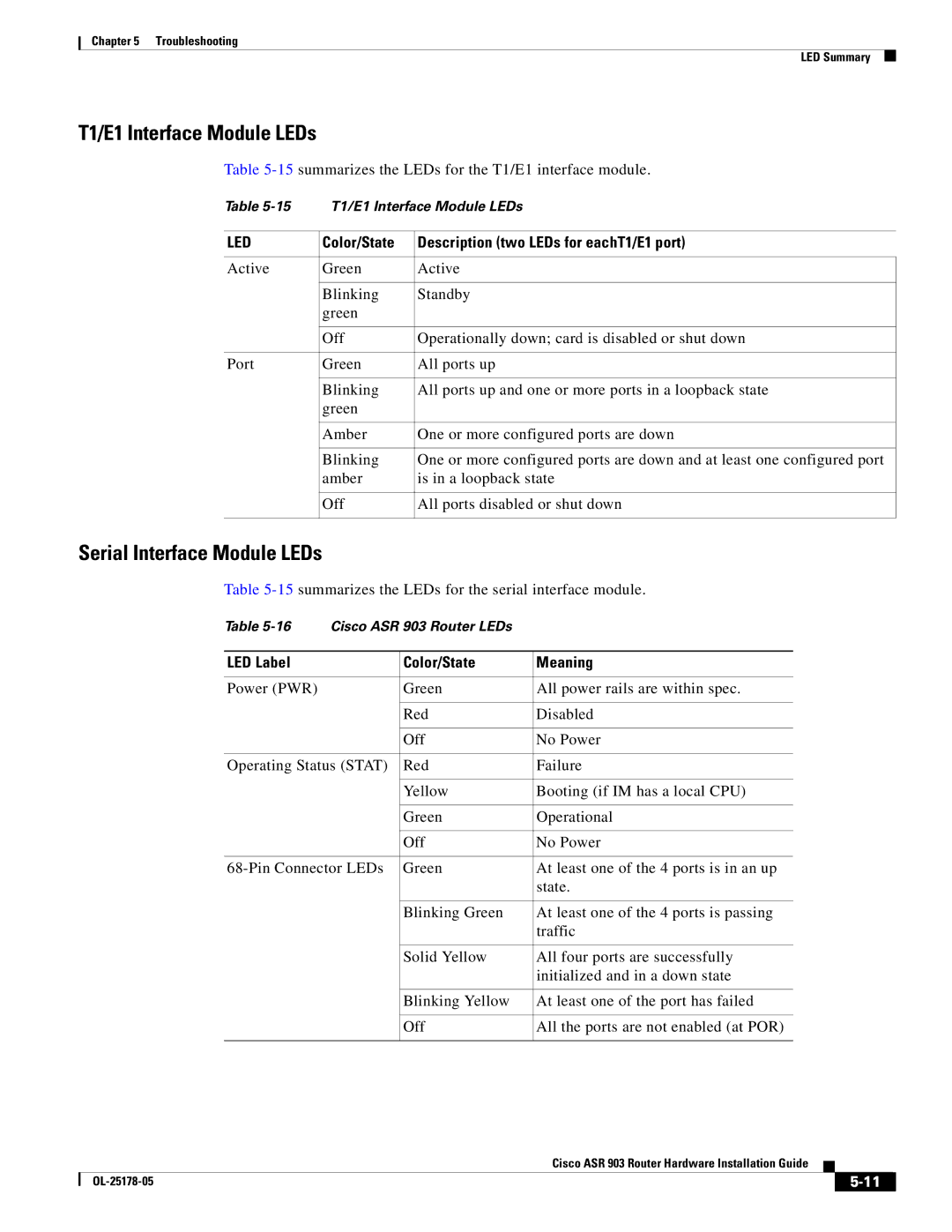
T1/E1 Interface Module LEDs
Table
Table | T1/E1 Interface Module LEDs | |
|
|
|
LED | Color/State | Description (two LEDs for eachT1/E1 port) |
|
|
|
Active | Green | Active |
|
|
|
| Blinking | Standby |
| green |
|
|
|
|
| Off | Operationally down; card is disabled or shut down |
|
|
|
Port | Green | All ports up |
|
|
|
| Blinking | All ports up and one or more ports in a loopback state |
| green |
|
|
|
|
| Amber | One or more configured ports are down |
|
|
|
| Blinking | One or more configured ports are down and at least one configured port |
| amber | is in a loopback state |
|
|
|
| Off | All ports disabled or shut down |
|
|
|
Serial Interface Module LEDs
Table
Table | Cisco ASR 903 Router LEDs |
| |
|
|
|
|
LED Label |
| Color/State | Meaning |
|
|
|
|
Power (PWR) |
| Green | All power rails are within spec. |
|
|
|
|
|
| Red | Disabled |
|
|
|
|
|
| Off | No Power |
|
|
| |
Operating Status (STAT) | Red | Failure | |
|
|
|
|
|
| Yellow | Booting (if IM has a local CPU) |
|
|
|
|
|
| Green | Operational |
|
|
|
|
|
| Off | No Power |
|
|
| |
Green | At least one of the 4 ports is in an up | ||
|
|
| state. |
|
|
|
|
|
| Blinking Green | At least one of the 4 ports is passing |
|
|
| traffic |
|
|
|
|
|
| Solid Yellow | All four ports are successfully |
|
|
| initialized and in a down state |
|
|
|
|
|
| Blinking Yellow | At least one of the port has failed |
|
|
|
|
|
| Off | All the ports are not enabled (at POR) |
|
|
|
|
|
| Cisco ASR 903 Router Hardware Installation Guide |
|
| |
|
|
| |||
|
|
|
| ||
|
|
|
| ||