Chapter 3 Installing the Cisco ASR 903 Router
Installing the Power Supply
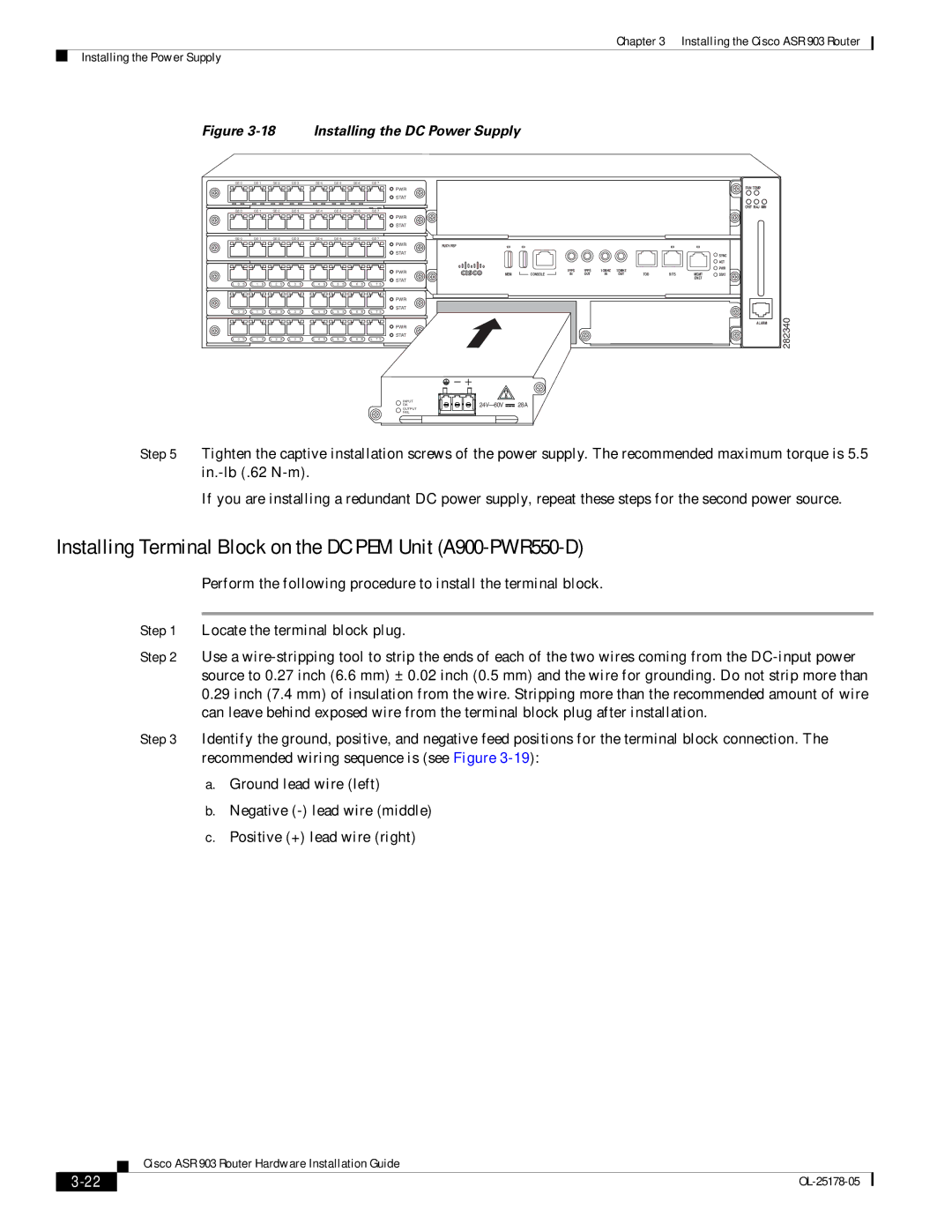
Figure 3-18 Installing the DC Power Supply
|
|
|
|
|
|
|
|
|
| ||||||||
|
|
|
|
|
|
| PWR |
|
|
|
|
|
|
|
|
| FAN TEMP |
|
|
|
|
|
|
| STAT |
|
|
|
|
|
|
|
|
|
|
|
|
|
|
|
|
|
|
|
|
|
|
|
|
|
|
| CRIT MAJ MIN |
|
|
|
|
|
|
|
|
|
| ||||||||
|
|
|
|
|
|
| PWR |
|
|
|
|
|
|
|
|
|
|
|
|
|
|
|
|
| STAT |
|
|
|
|
|
|
|
|
|
|
|
|
|
|
|
|
|
|
|
| ||||||||
|
|
|
|
|
|
| PWR | RUDY RSP |
|
|
|
|
|
|
|
|
|
|
|
|
|
|
|
| STAT |
|
|
|
|
|
|
|
|
| SYNC |
|
|
|
|
|
|
|
|
|
|
|
|
|
|
|
|
| |
|
|
|
|
|
|
|
|
|
|
|
|
|
|
|
|
| ACT |
|
|
|
|
|
|
| PWR |
|
| 1PPS | 1PPS | 1OMHZ | 1OMHZ |
|
|
| PWR |
|
|
|
|
|
|
| MEM | CONSOLE | TOD | BITS | MGMT | STAT | |||||
|
|
|
|
|
|
|
| IN | OUT | IN | OUT | ||||||
|
|
|
|
|
|
| STAT |
|
|
|
|
|
|
|
| ENET |
|
|
|
|
|
|
|
|
|
|
|
|
|
|
|
|
|
| |
L 0 S | L 1 S | L 2 S | L 3 S | L 4 S | L 5 S | L 6 S | L 7 S |
|
|
|
|
|
|
|
|
|
|
|
|
|
|
|
|
| PWR |
|
|
|
|
|
|
|
|
|
|
|
|
|
|
|
|
| STAT |
|
|
|
|
|
|
|
|
|
|
L 0 S | L 1 S | L 2 S | L 3 S | L 4 S | L 5 S | L 6 S | L 7 S |
|
|
|
|
|
|
|
|
|
|
|
|
|
|
|
|
| PWR |
|
|
|
|
|
|
|
|
| ALARM |
|
|
|
|
|
|
|
|
|
|
|
|
|
|
|
|
| |
|
|
|
|
|
|
| STAT |
|
|
|
|
|
|
|
|
|
|
L 0 S | L 1 S | L 2 S | L 3 S | L 4 S | L 5 S | L 6 S | L 7 S |
|
|
|
|
|
|
|
|
|
|
|
|
|
|
|
|
| INPUT | 28A |
|
|
|
|
|
|
|
| |
|
|
|
|
|
|
| OK |
|
|
|
|
|
|
|
|
OUTPUT
FAIL
282340
Step 5 Tighten the captive installation screws of the power supply. The recommended maximum torque is 5.5
If you are installing a redundant DC power supply, repeat these steps for the second power source.
Installing Terminal Block on the DC PEM Unit (A900-PWR550-D)
Perform the following procedure to install the terminal block.
Step 1 Locate the terminal block plug.
Step 2 Use a
0.29inch (7.4 mm) of insulation from the wire. Stripping more than the recommended amount of wire can leave behind exposed wire from the terminal block plug after installation.
Step 3 Identify the ground, positive, and negative feed positions for the terminal block connection. The recommended wiring sequence is (see Figure
a.Ground lead wire (left)
b.Negative
c.Positive (+) lead wire (right)
| Cisco ASR 903 Router Hardware Installation Guide |
|