Chapter 3 Installing the Cisco ASR 903 Router
Installing the Power Supply
Warning This product requires
Installing the AC Power Supply Module
Follow these steps to install the power supply module:
Step 1 Ensure that the system (earth) ground connection has been made. For ground connection installation instructions, see the “Installing the Chassis Ground Connection” section on page
Step 2 If necessary, remove the blank power supply filler plate from the chassis power supply bay opening by loosening the captive installation screws.
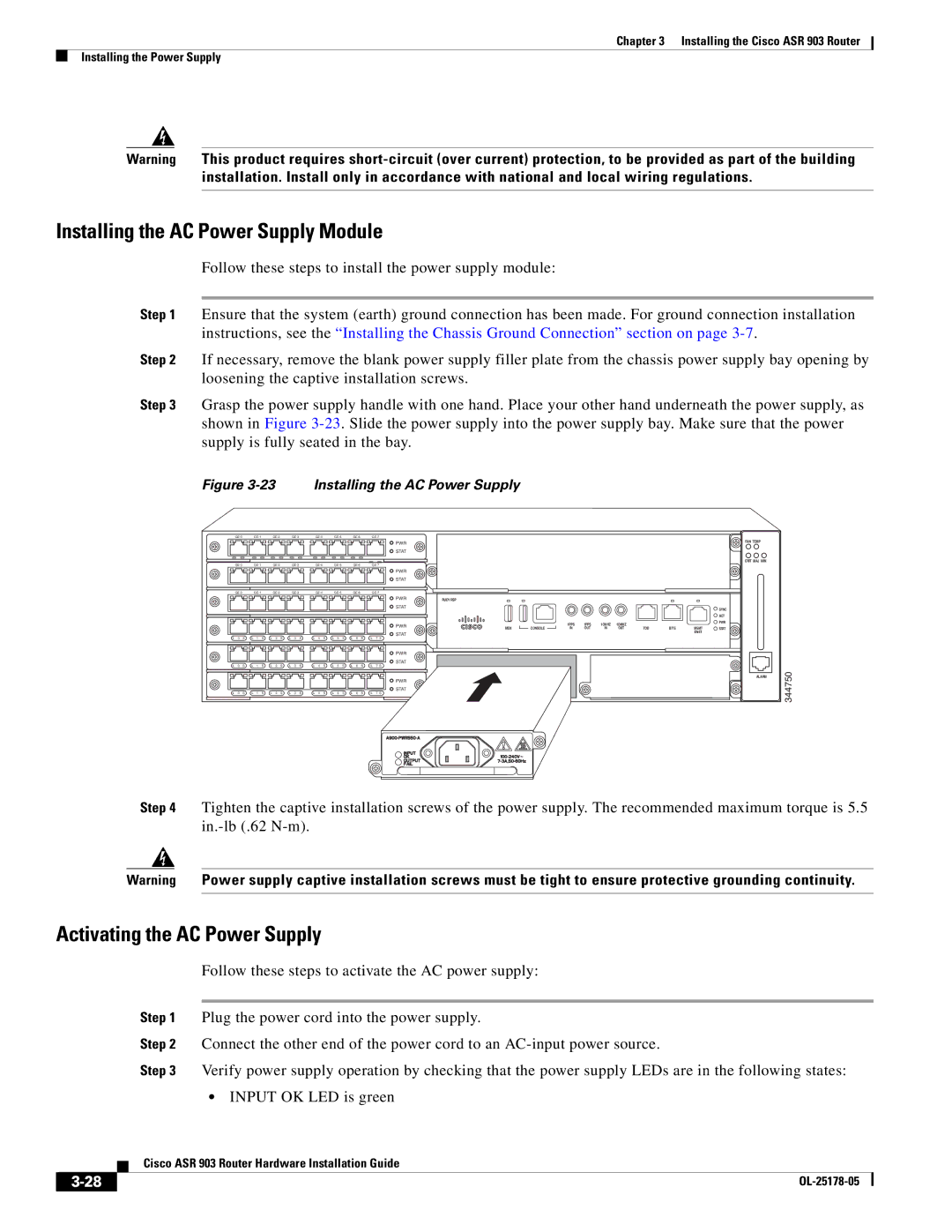
Step 3 Grasp the power supply handle with one hand. Place your other hand underneath the power supply, as shown in Figure
Figure 3-23 Installing the AC Power Supply
|
|
|
|
|
|
| PWR |
|
|
|
|
|
|
| STAT |
|
|
|
|
|
|
| PWR |
|
|
|
|
|
|
| STAT |
|
|
|
|
|
|
| PWR |
|
|
|
|
|
|
| STAT |
|
|
|
|
|
|
| PWR |
|
|
|
|
|
|
| STAT |
L 0 S | L 1 S | L 2 S | L 3 S | L 4 S | L 5 S | L 6 S | L 7 S |
|
|
|
|
|
|
| PWR |
|
|
|
|
|
|
| STAT |
L 0 S | L 1 S | L 2 S | L 3 S | L 4 S | L 5 S | L 6 S | L 7 S |
|
|
|
|
|
|
| PWR |
|
|
|
|
|
|
| STAT |
L 0 S | L 1 S | L 2 S | L 3 S | L 4 S | L 5 S | L 6 S | L 7 S |
RUDY RSP |
|
|
|
|
|
|
|
|
|
|
|
|
|
|
|
|
|
| SYNC |
|
|
|
|
|
|
|
|
| ACT |
|
| 1PPS | 1PPS | 1OMHZ | 1OMHZ |
|
|
| PWR |
MEM | CONSOLE | IN | OUT | IN | OUT | TOD | BITS | MGMT | STAT |
|
|
|
|
|
|
|
| ENET |
|
FAN TEMP
CRIT MAJ MIN
ALARM
344750
Step 4 Tighten the captive installation screws of the power supply. The recommended maximum torque is 5.5
Warning Power supply captive installation screws must be tight to ensure protective grounding continuity.
Activating the AC Power Supply
Follow these steps to activate the AC power supply:
Step 1 Plug the power cord into the power supply.
Step 2 Connect the other end of the power cord to an
Step 3 Verify power supply operation by checking that the power supply LEDs are in the following states:
•INPUT OK LED is green
| Cisco ASR 903 Router Hardware Installation Guide |
|