Chapter 3 Installing the Cisco ASR 903 Router
Installing the Fan Tray
Installing the Fan Tray
The fan tray is a modular unit that provides cooling to the Cisco ASR 903 Router. Follow these steps to install the fan tray in the chassis:
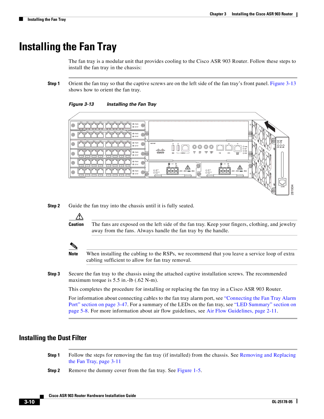
Step 1 Orient the fan tray so that the captive screws are on the left side of the fan tray’s front panel. Figure
Figure 3-13 Installing the Fan Tray
|
|
|
|
|
|
|
|
|
| ||||||||
|
|
|
|
|
|
| PWR |
|
|
|
|
|
|
|
|
|
|
|
|
|
|
|
|
| STAT |
|
|
|
|
|
|
|
|
|
|
|
|
|
|
|
|
|
|
|
| ||||||||
|
|
|
|
|
|
| PWR |
|
|
|
|
|
|
|
|
|
|
|
|
|
|
|
|
| STAT |
|
|
|
|
|
|
|
|
|
|
|
|
|
|
|
|
|
|
|
| ||||||||
|
|
|
|
|
|
| PWR | RUDY RSP |
|
|
|
|
|
|
|
|
|
|
|
|
|
|
|
| STAT |
|
|
|
|
|
|
|
|
| SYNC |
|
|
|
|
|
|
|
|
|
|
|
|
|
|
|
|
| ACT |
|
|
|
|
|
|
| PWR |
|
| 1PPS | 1PPS | 1OMHZ | 1OMHZ |
|
|
| PWR |
|
|
|
|
|
|
| MEM | CONSOLE | TOD | BITS | MGMT | STAT | |||||
|
|
|
|
|
|
|
| IN | OUT | IN | OUT | ||||||
|
|
|
|
|
|
| STAT |
|
|
|
|
|
|
|
| ENET |
|
|
|
|
|
|
|
|
|
|
|
|
|
|
|
|
|
| |
L 0 S | L 1 S | L 2 S | L 3 S | L 4 S | L 5 S | L 6 S | L 7 S |
|
|
|
|
|
|
|
|
|
|
|
|
|
|
|
|
| PWR |
|
|
|
|
|
|
|
|
|
|
|
|
|
|
|
|
| STAT |
|
|
|
|
|
|
|
|
|
|
L 0 S | L 1 S | L 2 S | L 3 S | L 4 S | L 5 S | L 6 S | L 7 S |
|
|
|
|
|
|
|
|
|
|
|
|
|
|
|
|
| PWR | INPUT | 28A |
| INPUT |
|
| 28A | |||
|
|
|
|
|
|
| OK |
| OK |
|
|
| |||||
|
|
|
|
|
|
| OUTPUT |
| OUTPUT |
|
| ||||||
|
|
|
|
|
|
| STAT | FAIL |
|
|
| FAIL |
|
|
|
| |
|
|
|
|
|
|
|
|
|
|
|
|
|
|
|
|
| |
L 0 S | L 1 S | L 2 S | L 3 S | L 4 S | L 5 S | L 6 S | L 7 S |
|
|
|
|
|
|
|
|
|
|
FAN TEMP
CRIT MAJ MIN
ALARM
281934
Step 2 Guide the fan tray into the chassis until it is fully seated.
Caution The fans are exposed on the left side of the fan tray. Keep your fingers, clothing, and jewelry away from the fans. Always handle the fan tray by the handle.
Note When installing the cabling to the RSPs, we recommend that you leave a service loop of extra cabling sufficient to allow for fan tray removal.
Step 3 Secure the fan tray to the chassis using the attached captive installation screws. The recommended maximum torque is 5.5
This completes the procedure for installing or replacing the fan tray in a Cisco ASR 903 Router.
For information about connecting cables to the fan tray alarm port, see “Connecting the Fan Tray Alarm Port” section on page
Installing the Dust Filter
Step 1 Follow the steps for removing the fan tray (if installed) from the chassis. See Removing and Replacing the Fan Tray, page
Step 2 Remove the dummy cover from the fan tray. See Figure
| Cisco ASR 903 Router Hardware Installation Guide |
|