Chapter 1 Cisco ASR 903 router Overview
Regulatory Compliance
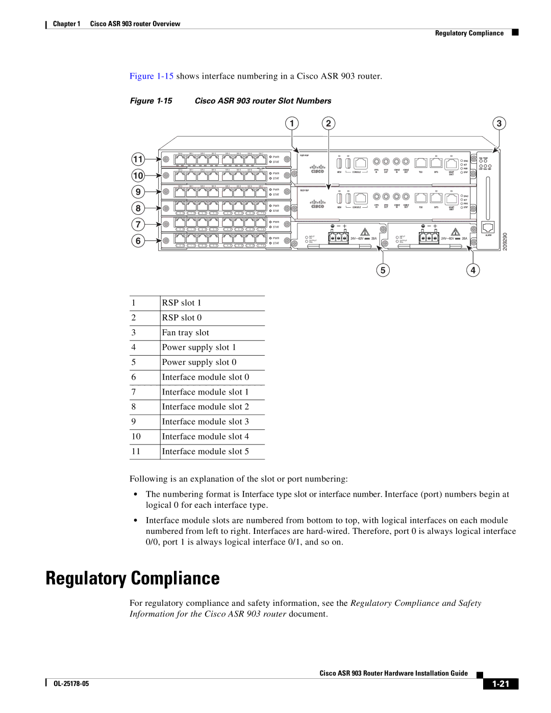
Figure 1-15 shows interface numbering in a Cisco ASR 903 router.
Figure 1-15 Cisco ASR 903 router Slot Numbers
|
|
|
|
|
|
|
|
|
|
|
|
|
|
|
|
|
|
|
|
|
|
|
| 1 | 2 |
|
|
|
|
|
|
|
|
|
| 3 |
11 |
|
|
|
|
|
|
|
|
|
|
|
|
|
|
| RUDY RSP |
|
|
|
|
|
|
|
|
|
|
| |||||||||
|
|
|
|
|
|
|
|
|
|
|
|
|
|
|
|
|
|
|
|
|
|
| PWR |
|
|
|
|
|
|
|
|
|
|
| ||
|
|
|
|
|
|
|
|
|
|
|
|
|
|
|
|
|
|
|
|
|
|
|
|
|
|
|
|
|
|
|
|
| FAN TEMP |
| ||
|
|
|
|
|
|
|
|
|
|
|
|
|
|
|
|
|
|
|
|
|
|
| STAT |
|
|
|
|
|
|
|
|
| SYNC |
|
| |
|
|
|
|
|
|
|
|
|
|
|
|
|
|
|
|
|
|
|
|
|
|
|
|
|
|
|
|
|
|
|
| ACT |
|
| ||
|
|
|
|
|
|
|
|
|
|
|
|
|
|
|
|
|
|
|
|
|
|
|
|
|
|
|
|
|
|
|
|
|
|
|
| |
10 |
|
|
|
|
|
|
|
|
|
|
|
|
|
|
|
|
| 1PPS | 1PPS | 1OMHZ | 1OMHZ |
|
|
| PWR | CRIT MAJ MIN |
| |||||||||
|
|
|
|
|
|
|
|
|
|
|
|
|
|
|
|
|
|
|
|
|
|
| PWR | MEM | CONSOLE | IN | OUT | IN | OUT | TOD | BITS | MGMT | STAT |
|
| |
|
|
|
|
|
|
|
|
|
|
|
|
|
|
|
|
|
|
|
|
|
|
|
|
|
|
|
|
|
|
| ENET |
|
|
| ||
|
|
|
|
|
|
|
|
|
|
|
|
|
|
|
|
|
|
|
|
|
|
| STAT |
|
|
|
|
|
|
|
|
|
|
|
| |
9 |
|
|
|
|
|
|
|
|
|
|
|
|
|
|
|
|
|
|
|
|
|
|
|
|
|
|
| |||||||||
|
|
|
|
|
|
|
|
|
|
|
|
|
|
|
|
|
|
|
|
|
|
| PWR | RUDY RSP |
|
|
|
|
|
|
|
|
|
|
| |
|
|
|
|
|
|
|
|
|
|
|
|
|
|
|
|
|
|
|
|
|
|
| STAT |
|
|
|
|
|
|
|
|
| SYNC |
|
| |
|
|
|
|
|
|
|
|
|
|
|
|
|
|
|
|
|
|
|
|
|
|
|
|
|
|
|
|
|
|
|
|
|
| ACT |
|
|
8 |
|
|
|
|
|
|
|
|
|
|
|
|
|
|
|
|
|
|
|
|
|
|
| PWR |
|
| 1PPS | 1PPS | 1OMHZ | 1OMHZ |
|
|
| PWR |
|
|
|
|
|
|
|
|
|
|
|
|
|
|
|
|
|
|
|
|
|
|
|
|
|
|
|
|
|
|
|
|
| ||||||
|
|
|
|
|
|
|
|
|
|
|
|
|
|
|
|
|
|
|
|
|
|
| MEM | CONSOLE | IN | OUT | IN | OUT | TOD | BITS | MGMT | STAT |
|
| ||
|
|
|
|
|
|
|
|
|
|
|
|
|
|
|
|
|
|
|
|
|
|
| STAT |
|
|
|
|
|
|
|
| ENET |
|
|
| |
L 0 S | L 1 S | L 2 S | L 3 S | L 4 S | L 5 S | L 6 S | L 7 S |
|
|
|
|
|
|
|
|
|
|
|
| |||||||||||||||||
7 |
|
|
|
|
|
|
|
|
|
|
|
|
|
|
|
|
|
|
|
|
|
|
| PWR |
|
|
|
|
|
|
|
|
|
|
|
|
L | 0 | S | L | 1 | S | L | 2 | S | L | 3 | S | L | 4 | S | L | 5 | S | L | 6 | S | L | 7 S | STAT |
|
|
|
|
|
|
|
|
|
|
|
| |
6 |
|
|
|
|
|
|
|
|
|
|
|
|
|
|
|
|
|
|
|
|
|
|
|
| INPUT |
|
|
| INPUT |
|
|
|
| ALARM | 209290 | |
|
|
|
|
|
|
|
|
|
|
|
|
|
|
|
|
|
|
|
|
|
|
| PWR | OK | 28A |
| OK |
|
|
| 28A |
| ||||
|
|
|
|
|
|
|
|
|
|
|
|
|
|
|
|
|
|
|
|
|
|
| OUTPUT |
| OUTPUT |
|
|
| ||||||||
|
|
|
|
|
|
|
|
|
|
|
|
|
|
|
|
|
|
|
|
|
|
| STAT | FAIL |
|
|
| FAIL |
|
|
|
|
| |||
L | 0 | S | L | 1 | S | L | 2 | S | L | 3 | S | L | 4 | S | L | 5 | S | L | 6 | S | L | 7 S |
|
|
|
|
|
|
|
|
|
|
| |||
|
|
|
|
|
|
|
|
|
|
|
|
|
|
|
|
|
|
|
|
|
|
|
|
|
|
|
|
|
|
|
|
|
|
|
| |
|
|
|
|
|
|
|
|
|
|
|
|
|
|
|
|
|
|
|
|
|
|
|
|
|
|
|
| 5 |
|
|
|
|
|
| 4 |
|
1 | RSP slot 1 |
|
|
2 | RSP slot 0 |
|
|
3 | Fan tray slot |
|
|
4 | Power supply slot 1 |
|
|
5 | Power supply slot 0 |
|
|
6 | Interface module slot 0 |
|
|
7 | Interface module slot 1 |
|
|
8 | Interface module slot 2 |
|
|
9 | Interface module slot 3 |
|
|
10 | Interface module slot 4 |
|
|
11 | Interface module slot 5 |
|
|
Following is an explanation of the slot or port numbering:
•The numbering format is Interface type slot or interface number. Interface (port) numbers begin at logical 0 for each interface type.
•Interface module slots are numbered from bottom to top, with logical interfaces on each module numbered from left to right. Interfaces are
Regulatory Compliance
For regulatory compliance and safety information, see the Regulatory Compliance and Safety
Information for the Cisco ASR 903 router document.
Cisco ASR 903 Router Hardware Installation Guide
|
| ||
|
|