Chapter 5 Troubleshooting
LED Summary
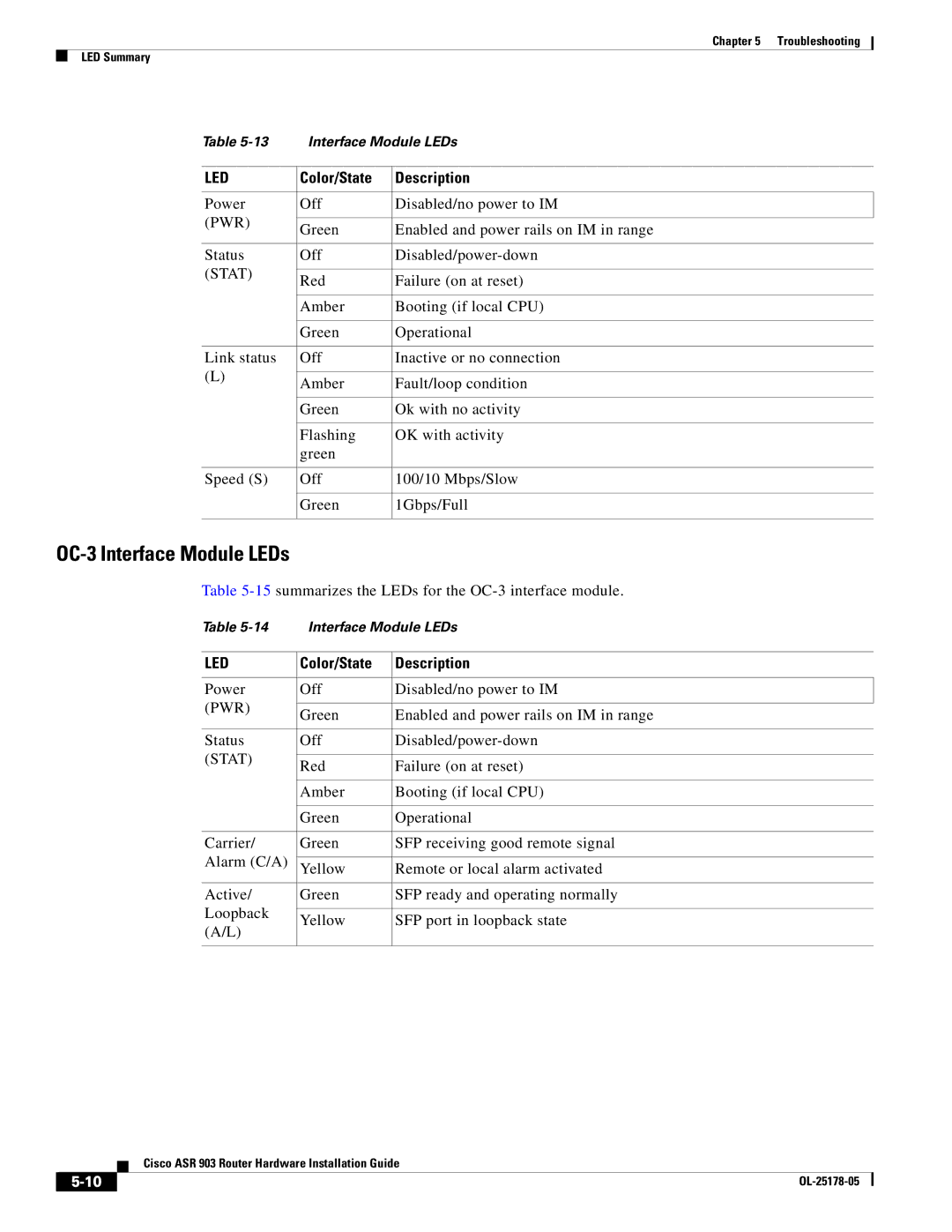
Table | Interface Module LEDs | ||
|
|
| |
LED | Color/State | Description | |
|
|
| |
Power | Off | Disabled/no power to IM | |
(PWR) |
|
| |
Green | Enabled and power rails on IM in range | ||
| |||
|
|
| |
Status | Off | ||
(STAT) |
|
| |
Red | Failure (on at reset) | ||
| |||
|
|
| |
| Amber | Booting (if local CPU) | |
|
|
| |
| Green | Operational | |
|
|
| |
Link status | Off | Inactive or no connection | |
(L) |
|
| |
Amber | Fault/loop condition | ||
| |||
|
|
| |
| Green | Ok with no activity | |
|
|
| |
| Flashing | OK with activity | |
| green |
| |
|
|
| |
Speed (S) | Off | 100/10 Mbps/Slow | |
|
|
| |
| Green | 1Gbps/Full | |
|
|
| |
OC-3 Interface Module LEDs
Table
Table | Interface Module LEDs | ||
|
|
| |
LED | Color/State | Description | |
|
|
| |
Power | Off | Disabled/no power to IM | |
(PWR) |
|
| |
Green | Enabled and power rails on IM in range | ||
| |||
|
|
| |
Status | Off | ||
(STAT) |
|
| |
Red | Failure (on at reset) | ||
| |||
|
|
| |
| Amber | Booting (if local CPU) | |
|
|
| |
| Green | Operational | |
|
|
| |
Carrier/ | Green | SFP receiving good remote signal | |
Alarm (C/A) |
|
| |
Yellow | Remote or local alarm activated | ||
|
|
| |
Active/ | Green | SFP ready and operating normally | |
Loopback |
|
| |
Yellow | SFP port in loopback state | ||
(A/L) | |||
|
| ||
|
|
| |
| Cisco ASR 903 Router Hardware Installation Guide |
|