Chapter 3 Installing the Cisco ASR 903 Router
Installing the Power Supply
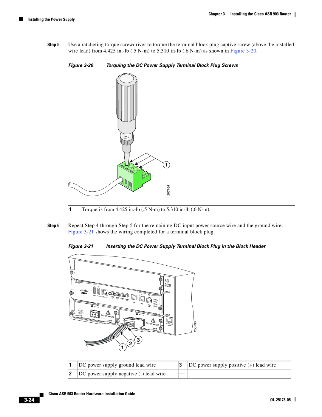
Step 5 Use a ratcheting torque screwdriver to torque the terminal block plug captive screw (above the installed wire lead) from 4.425
Figure 3-20 Torquing the DC Power Supply Terminal Block Plug Screws
1
1
207764
Torque is from 4.425
Step 6 Repeat Step 4 through Step 5 for the remaining DC input power source wire and the ground wire. Figure
Figure 3-21 Inserting the DC Power Supply Terminal Block Plug in the Block Header
RUDY RSP
INPUT
OK
OUTPUT
FAIL
MEM |
|
|
|
|
|
CONSOLE | 1PPS | 1PPS |
|
|
|
| IN | 1OMHZ |
|
| |
|
| OUT | 1OMHZ |
| |
|
|
| IN | SYNC | |
|
|
|
| OUT | |
|
|
|
| TOD | ACT |
|
|
|
| BITS | PWR |
|
|
|
| MGMT | |
|
|
|
| ENET | STAT |
28A |
| |
|
| |
| 28A | |
|
|
FAN TEMP | |
CRIT | MAJ MIN |
| |
ALARM
255730
2
1
3
| 1 | DC power supply ground lead wire | 3 | DC power supply positive (+) lead wire |
| ||||
|
|
|
|
|
| ||||
2 | DC power supply negative | — | — | ||||||
|
|
|
|
|
|
|
|
|
|
|
|
| Cisco ASR 903 Router Hardware Installation Guide |
|
|
|
| ||
|
|
|
|
|
|
| |||
|
|
|
|
|
|
|
|
|
|
|
|
|
|
|
|
|
| ||
|
|
|
|
|
|
| |||
