Chapter 5 Troubleshooting
Pinouts
Table |
| T1/E1 Interface Pinouts (continued) |
|
|
|
| |||
|
|
|
|
|
|
|
|
| |
| Board |
| Telco | Jack | Board |
| Telco | Jack | |
Line | PIns |
| Signal Name | TX | Pin | Pins | Signal Name | RX | Pin |
|
|
|
|
|
|
|
|
|
|
Line 15 | 61 |
| TX_RING_P16 | 28 | 1 | 57 | RX_RING_P16 | 28 | 4 |
|
|
|
|
|
|
|
|
|
|
| 11 |
| TX_TIP_P16 | 3 | 2 | 7 | RX_TIP_P16 | 3 | 5 |
|
|
|
|
|
|
|
|
|
|
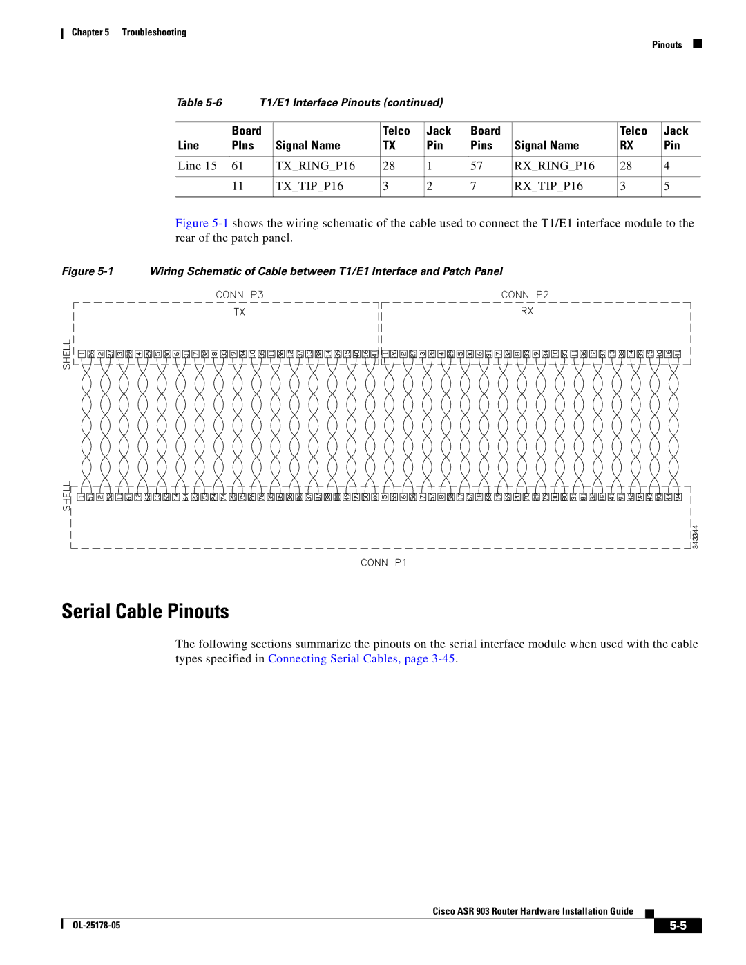
Figure 5-1 shows the wiring schematic of the cable used to connect the T1/E1 interface module to the rear of the patch panel.
Figure 5-1 Wiring Schematic of Cable between T1/E1 Interface and Patch Panel
![]()
![]()
![]()
![]()
![]()
![]()
![]()
![]()
![]()
![]()
![]()
![]()
![]()
![]()
![]()
![]()
![]()
![]()
![]()
![]()
![]()
![]()
![]()
![]()
![]()
![]()
![]()
![]()
![]()
![]()
![]()
![]()
![]()
![]()
![]()
![]()
![]()
![]()
![]()
![]()
![]() 343344
343344
Serial Cable Pinouts
The following sections summarize the pinouts on the serial interface module when used with the cable types specified in Connecting Serial Cables, page
Cisco ASR 903 Router Hardware Installation Guide
|
| ||
|
|