Chapter 5 Troubleshooting
Pinouts
Table | BITS Port Pinout (continued) |
| ||
|
|
|
| |
Pin | Signal Name | Direction | Description | |
|
|
|
|
|
5 | TX Tip |
| Output | TX Tip |
|
|
|
|
|
6 |
|
|
| Not used |
|
|
|
|
|
7 |
|
|
| Not used |
|
|
|
|
|
8 |
|
|
| Not used |
|
|
|
|
|
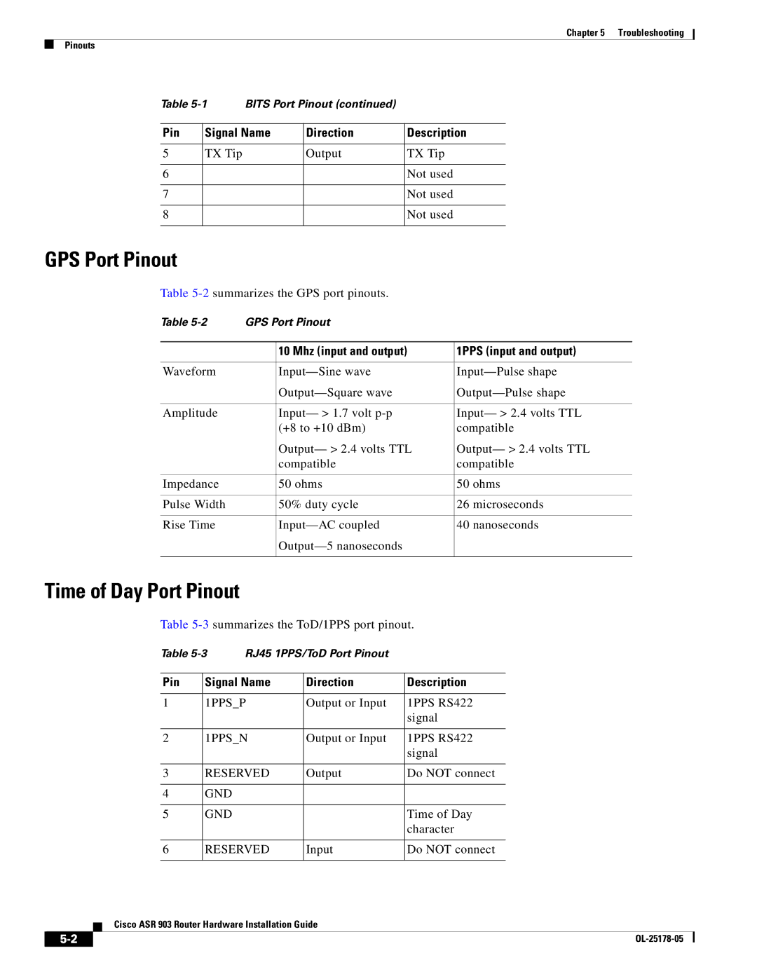
GPS Port Pinout
Table
Table | GPS Port Pinout |
| |
|
|
|
|
|
| 10 Mhz (input and output) | 1PPS (input and output) |
|
|
|
|
Waveform |
| ||
|
| ||
|
|
|
|
Amplitude |
| Input— > 1.7 volt | Input— > 2.4 volts TTL |
|
| (+8 to +10 dBm) | compatible |
|
| Output— > 2.4 volts TTL | Output— > 2.4 volts TTL |
|
| compatible | compatible |
|
|
|
|
Impedance |
| 50 ohms | 50 ohms |
|
|
|
|
Pulse Width |
| 50% duty cycle | 26 microseconds |
|
|
|
|
Rise Time |
| 40 nanoseconds | |
|
|
| |
|
|
|
|
Time of Day Port Pinout
Table
|
|
|
| Table | RJ45 1PPS/ToD Port Pinout |
|
|
| ||
|
|
|
|
|
|
|
|
| ||
|
|
|
| Pin | Signal Name | Direction | Description | |||
|
|
|
|
|
| |||||
1 | 1PPS_P | Output or Input | 1PPS RS422 | |||||||
|
|
|
|
|
|
|
| signal | ||
|
|
|
|
|
| |||||
2 | 1PPS_N | Output or Input | 1PPS RS422 | |||||||
|
|
|
|
|
|
|
| signal | ||
|
|
|
|
|
| |||||
3 | RESERVED | Output | Do NOT connect | |||||||
|
|
|
|
|
|
|
| |||
4 | GND |
|
|
|
|
| ||||
|
|
|
|
|
|
| ||||
5 | GND |
|
| Time of Day | ||||||
|
|
|
|
|
|
|
| character | ||
|
|
|
|
|
| |||||
6 | RESERVED | Input | Do NOT connect | |||||||
|
|
|
|
|
|
|
|
|
| |
|
|
| Cisco ASR 903 Router Hardware Installation Guide |
|
|
| ||||
|
|
|
|
|
| |||||
|
|
|
|
|
|
|
|
|
|
|
|
|
|
|
|
|
|
|
|
| |
|
|
|
|
|
|
|
| |||