Chapter 5 Troubleshooting
LED Summary
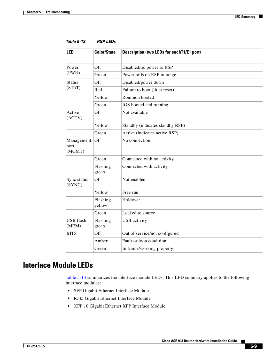
Table | RSP LEDs |
| |
|
|
| |
LED | Color/State | Description (two LEDs for eachT1/E1 port) | |
|
|
| |
|
|
| |
Power | Off | Disabled/no power to RSP | |
(PWR) |
|
| |
Green | Power rails on RSP in range | ||
| |||
|
|
| |
Status | Off | Disabled/power down | |
(STAT) |
|
| |
Red | Failure to boot (lit at reset) | ||
| |||
|
|
| |
| Yellow | Rommon booted | |
|
|
| |
| Green | IOS booted and running | |
|
|
| |
Active | Off | Not available | |
(ACTV) |
|
| |
|
|
| |
| Yellow | Standby (indicates standby RSP) | |
|
|
| |
| Green | Active (indicates active RSP) | |
|
|
| |
Management | Off | No connection | |
port |
|
| |
(MGMT) |
|
| |
|
|
| |
| Green | Connected with no activity | |
|
|
| |
| Flashing | Connected with activity | |
| green |
| |
|
|
| |
Sync status | Off | Not enabled | |
(SYNC) |
|
| |
|
|
| |
| Yellow | Free run | |
|
|
| |
| Flashing | Holdover | |
| yellow |
| |
|
|
| |
| Green | Locked to source | |
|
|
| |
USB flash | Flashing | USB activity | |
(MEM) | green |
| |
|
|
| |
BITS | Off | Out of service/not configured | |
|
|
| |
| Amber | Fault or loop condition | |
|
|
| |
| Green | In frame/working properly | |
|
|
|
Interface Module LEDs
Table
•SFP Gigabit Ethernet Interface Module
•RJ45 Gigabit Ethernet Interface Module
•XFP 10 Gigabit Ethernet XFP Interface Module
Cisco ASR 903 Router Hardware Installation Guide
|
| ||
|
|