Manuals
/
Brands
/
Computer Equipment
/
Network Router
/
Cisco Systems
/
Computer Equipment
/
Network Router
Cisco Systems
ASR 903
- page 30
1
30
132
132
Download
132 pages, 5.27 Mb
1-18
Cisco ASR 903 Router Hardware Installation Guide
OL-25178-05
Chapter1 Cisc
o ASR 903 router Overview
CiscoASR 903 router Features
Figure1-12
Serial
Interface Module
Figure 1-13 provides an overview of the CiscoASR 903 router front panel.
303338
STAT
PWR
A900-IMASER14A/S
J0-J3
J4-J7
J0-J3
J9
J10
J11
J13
J12
Contents
Main
Page
CONTENTS
Page
Page
Page
Page
Page
About this Book
Document Revision History
Document Audience
Document Organization
Document Conventions
Obtaining Documentation and Submitting a Service Request
Page
Cisco ASR 903 router Overview
Cisco ASR 903 router Features
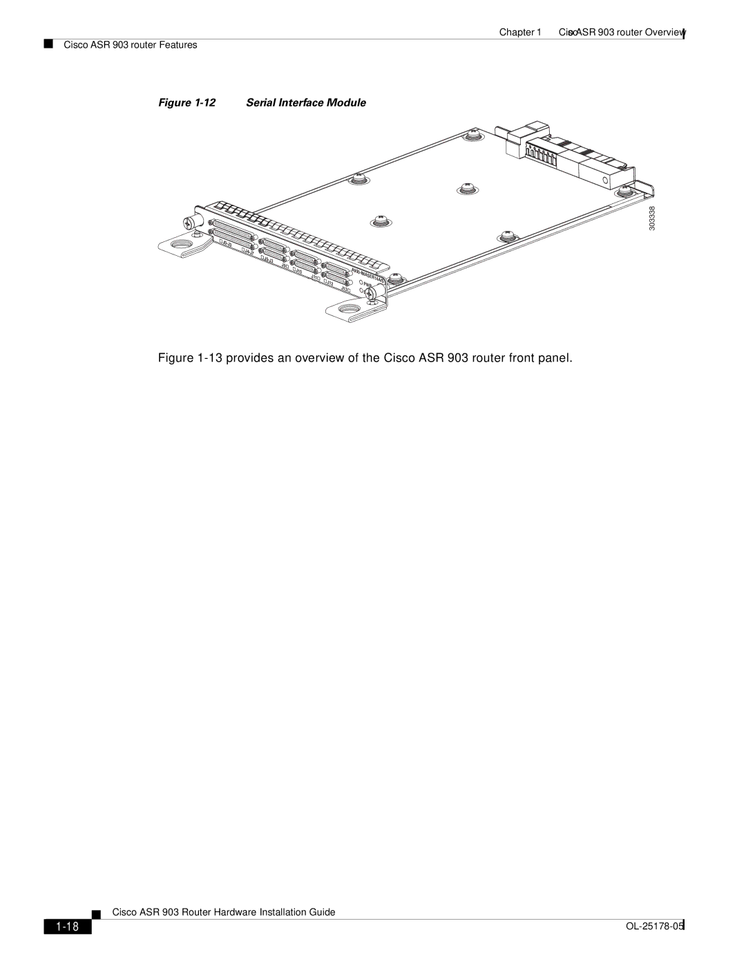
System Specifications
1 32
4
Power Supply Features
Redundancy
Dying Gasp
Status LEDs
DC Power Specifications
Page
AC Power Specifications
Fan Tray
Fan Tray (A903-FAN)
Fan Tray (A903-FAN-E)
Dust Filter (A903-FAN-F)
Air Plenum
RSP Modules
Supported RSPs
Supported RSP Features
RSP Redundancy
Network Timing Interfaces
RSP Interfaces
Interface Modules
31 2 4 5 6 7 8 9 10
Gigabit Ethernet SFP Interface Module
Supported SFP Modules
Gigabit Ethernet RJ45 Interface Module
10 Gigabit Ethernet XFP Interface Module
Supported XFP Modules
Page
T1/E1 Interface Module
OC-3 Interface Module
Supported SFP Modules
Serial Interface Module
Page
Supported Standards
6
1 2 3 4
5
Temperature Sensor
Interface Numbering
Regulatory Compliance
2 31
45
11 10 9 8 7 6
Page
Preparing for Installation
Safety Guidelines
2-2
Standard Warning Statements
Safety Guidelines for Personal Safety and Equipment Protection
Safety Precautions for Module Installation and Removal
2-4
Safety with Electricity
2-5
2-6
Page
Power Supply Considerations
Preventing ESD Damage
Site Planning
General Precautions
Site Planning Checklist
Site Selection Guidelines
Environmental Requirements
Physical Characteristics
Air Flow Guidelines
Air exhaust
Room air
Air Flow Guidelines for Enclosed Rack Installation
Floor Loading Considerations
Site Power Guidelines
Electrical Circuit Requirements
Site Cabling Guidelines
Asynchronous Terminal Connections
Interference Considerations
Electromagnetic Interference
Radio Frequency Interference
Lightning and AC Power Fault Interference
Rack-Mounting Guidelines
Precautions for Rack-Mounting
Rack Selection Guidelines
Equipment Rack Guidelines
Locating for Safety
Locating for Easy Maintenance
Locating for Proper Airflow
Installation Checklist
Creating a Site Log
Receiving the Cisco ASR 903 Router
Chassis-Lifting Guidelines
Tools and Equipment
Unpacking and Verifying the Shipped Contents
Page
Installing the Cisco ASR 903 Router
Prerequisites
Installing the Router in a Rack
Installing the Chassis Brackets
Installing the Router Chassis in the Rack
Installing the Chassis in the Air Plenum
Attaching the Cable Management Brackets
Page
3-7
Installing the Chassis Ground Connection
24V60V 28A
1 Grounding lug (300 mm ETSI cabinet)
Installing the Chassis Ground Connection
300 mm ETSI cabinetAttach the grounding lug on the rack-mount bracket on the front of the
router, as shown in Figure3-10.
Page
Page
Installing the Fan Tray
Installing the Dust Filter
Removing the Dust Filter
Dust Filter Maintenance
Removing and Replacing the Fan Tray
Page
RSP Installation
Installing an RSP Module
Removing an RSP Module
Hot-Swapping an RSP Module
Interface Module Installation
Installing an Interface Module
Removing an Interface Module
Hot-Swapping an Interface Module
Installing the Power Supply
Preventing Power Loss
Power Connection Guidelines
Guidelines for DC-Powered Systems
Guidelines for AC-Powered Systems
Installing the DC Power Supply
Installing the DC Power Supply Module
Installing Terminal Block on the DC PEM Unit (A900-PWR550-D)
Page
3-24
Installing the Power Supply
ALARM
24V60V 28A
Figure3-21 Inserting the DC Power Supply Terminal Block Plug in the Block Header
Installing Terminal Block Connector on the DC PEM Unit (A900-PWR550-D-E)
Tools
Activating the DC Power Supply
Removing and Replacing the DC Power Supply
Installing the AC power Supply
Installing the AC Power Supply Module
Activating the AC Power Supply
Removing and Replacing the AC Power Supply
Connecting the Cisco ASR 903 Router to the Network
Connecting Console Cables
Connecting to the Serial Port using Microsoft Windows
3-32
Connecting the Cisco ASR 903 Router to the Network
MEM
ALARM
Figure3-24 Connecting the USB Console Cable to the CiscoASR 903 Router
Connecting to the Console Port using Mac OS X
Connecting to the Console Port using Linux
Installing the Cisco Microsoft Windows USB Device Driver
Installing the Cisco Microsoft Windows XP USB Driver
Installing the Cisco Microsoft Windows 2000 USB Driver
Installing the Cisco Microsoft Windows Vista USB Driver
Uninstalling the Cisco Microsoft Windows USB Driver
Uninstalling the Cisco Microsoft Windows XP and 2000 USB Driver
Uninstalling the Cisco Microsoft Windows Vista USB Driver
Connecting to the Auxiliary Port
3-37
Connecting the Cisco ASR 903 Router to the Network
MEM
ALARM
To connect a modem to the router, follow these steps:
Connecting a Management Ethernet Cable
Installing and Removing SFP and XFP Modules
Connecting a USB Flash Device
Removing a USB Flash Device
Connecting Timing Cables
Connecting Cables to the BITS Interface
Page
Connecting Cables to a GPS Interface
Connecting Cables to the Input 10Mhz or 1PPS Interface
Connecting Cables to the Output 10Mhz or 1PPS Interface
Connecting Cables to the ToD Interface
Connecting Ethernet Cables
Connecting Cables to SFP Modules
Connecting T1/E1 cables
Installing the Cable Connector
RJ45 Cable Pinouts
Connecting Cables to the Patch Panel
Recommended Patch Panel
Connecting Serial Cables
Page
Connecting the Fan Tray Alarm Port
Connector and Cable Specifications
Page
Cisco ASR 903 Router Initial Configuration
Checking Conditions Prior to System Startup
Powering Up the Cisco ASR 903 Router
4-3
4-4
Verifying the Front Panel LEDs
Verifying the Hardware Configuration
Checking Hardware and Software Compatibility
Configuring the Cisco ASR 903 Router at Startup
Using the Console Interface
Configuring Global Parameters
Checking the Running Configuration Settings
Saving the Running Configuration to NVRAM
Safely Powering Off the Cisco ASR 903 Router
Troubleshooting
Pinouts
BITS Port Pinout
GPS Port Pinout
Time of Day Port Pinout
Alarm Port Pinout
Console/Aux RJ45 RS232 Serial Port Pinout
T1/E1 Port Pinout
Serial Cable Pinouts
DB-9 Connector Pinouts
RJ-45 Connector Pinouts
Management Ethernet Port Pinout
USB Console Port Pinout
USB Flash/MEM Port Pinout
Fiber-Optic Specifications
LED Summary
RSP LEDs
Interface Module LEDs
OC-3 Interface Module LEDs
T1/E1 Interface Module LEDs
Serial Interface Module LEDs
Power Supply LEDs
Fan Tray LEDs
Alarm Conditions
Page
APPENDIX
Site Log and Manufactures
Page
Manufactures
Page
INDEX
A
B
C
N
P
R
S