Chapter 5 Troubleshooting
Pinouts
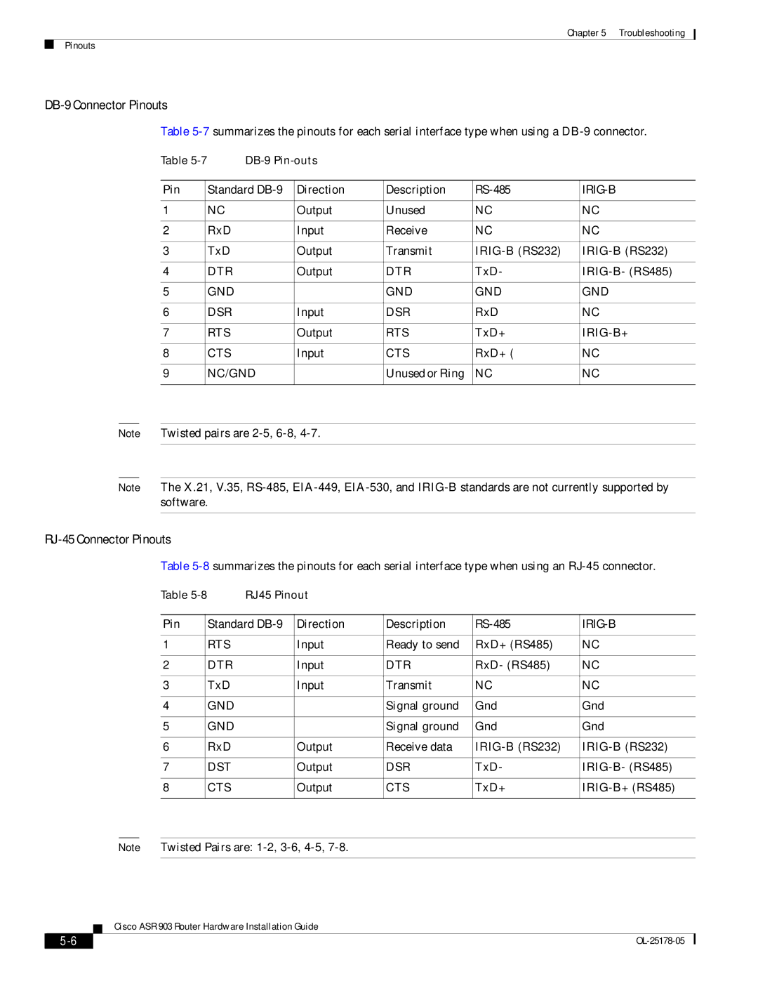
DB-9 Connector Pinouts
Table
Table |
|
|
| |||
|
|
|
|
|
| |
Pin |
| Standard | Direction | Description |
|
|
|
|
|
|
|
|
|
1 |
| NC | Output | Unused | NC | NC |
|
|
|
|
|
|
|
2 |
| RxD | Input | Receive | NC | NC |
|
|
|
|
|
|
|
3 |
| TxD | Output | Transmit | ||
|
|
|
|
|
|
|
4 |
| DTR | Output | DTR | TxD- | |
|
|
|
|
|
|
|
5 |
| GND |
| GND | GND | GND |
|
|
|
|
|
|
|
6 |
| DSR | Input | DSR | RxD | NC |
|
|
|
|
|
|
|
7 |
| RTS | Output | RTS | TxD+ | |
|
|
|
|
|
|
|
8 |
| CTS | Input | CTS | RxD+ ( | NC |
|
|
|
|
|
|
|
9 |
| NC/GND |
| Unused or Ring | NC | NC |
|
|
|
|
|
|
|
Note Twisted pairs are
Note The X.21, V.35,
RJ-45 Connector Pinouts
Table
Table | RJ45 Pinout |
|
|
| ||
|
|
|
|
|
| |
Pin |
| Standard | Direction | Description | ||
|
|
|
|
|
|
|
1 |
| RTS | Input | Ready to send | RxD+ (RS485) | NC |
|
|
|
|
|
|
|
2 |
| DTR | Input | DTR | RxD- (RS485) | NC |
|
|
|
|
|
|
|
3 |
| TxD | Input | Transmit | NC | NC |
|
|
|
|
|
|
|
4 |
| GND |
| Signal ground | Gnd | Gnd |
|
|
|
|
|
|
|
5 |
| GND |
| Signal ground | Gnd | Gnd |
|
|
|
|
|
|
|
6 |
| RxD | Output | Receive data | ||
|
|
|
|
|
|
|
7 |
| DST | Output | DSR | TxD- | |
|
|
|
|
|
|
|
8 |
| CTS | Output | CTS | TxD+ | |
|
|
|
|
|
|
|
Note Twisted Pairs are:
Cisco ASR 903 Router Hardware Installation Guide
|
| |
|