Chapter 4 Connecting the Cisco uBR7225VXR Router to the Cable Headend
Measuring the Downstream RF Signal
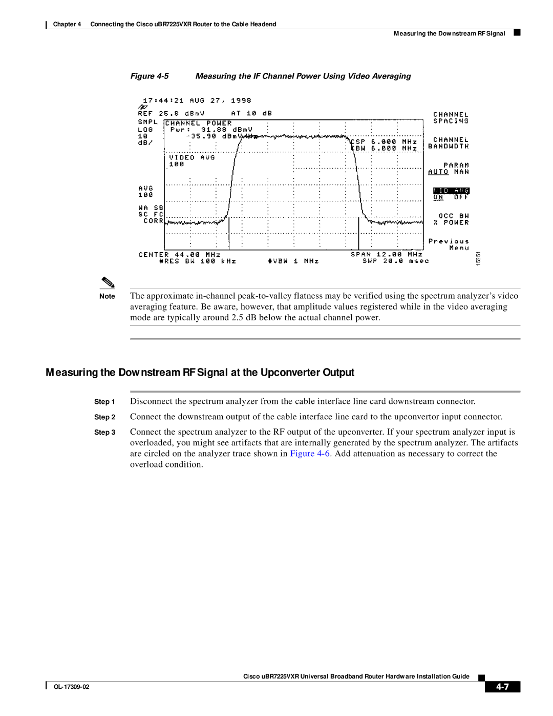
Figure 4-5 Measuring the IF Channel Power Using Video Averaging
Note The approximate
Measuring the Downstream RF Signal at the Upconverter Output
Step 1 Disconnect the spectrum analyzer from the cable interface line card downstream connector.
Step 2 Connect the downstream output of the cable interface line card to the upconvertor input connector.
Step 3 Connect the spectrum analyzer to the RF output of the upconverter. If your spectrum analyzer input is overloaded, you might see artifacts that are internally generated by the spectrum analyzer. The artifacts are circled on the analyzer trace shown in Figure
Cisco uBR7225VXR Universal Broadband Router Hardware Installation Guide
|
|
| |
|
|