Appendix B RF Specifications
DOCSIS 1.1 Transmission Characteristics
DOCSIS 1.1 Transmission Characteristics
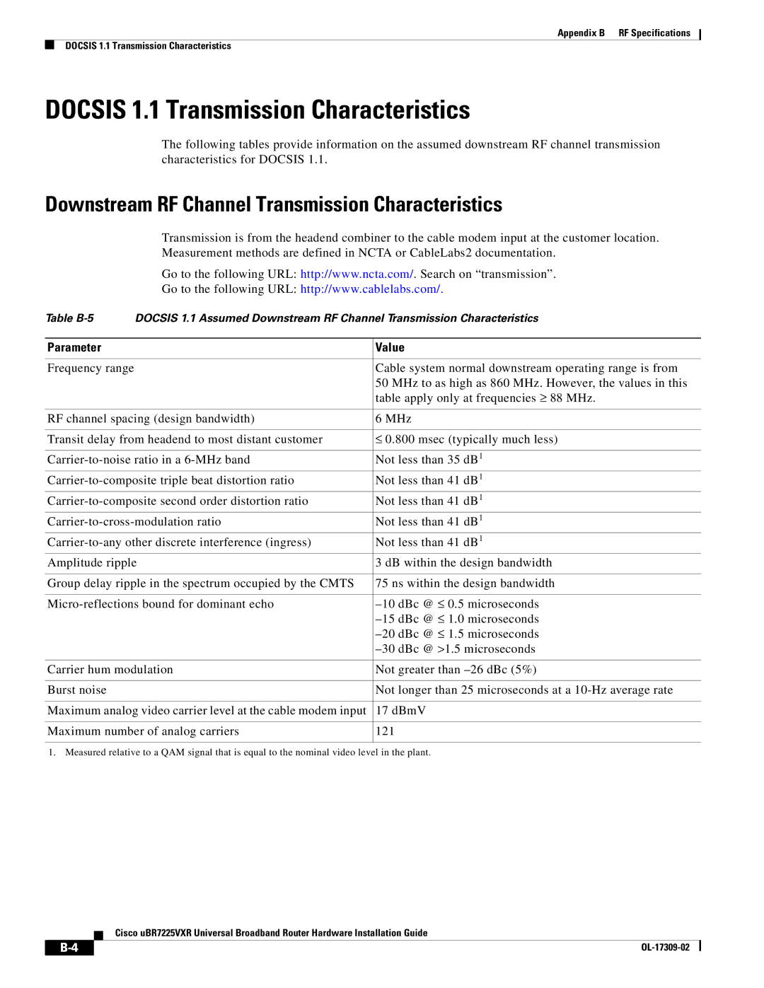
The following tables provide information on the assumed downstream RF channel transmission characteristics for DOCSIS 1.1.
Downstream RF Channel Transmission Characteristics
Transmission is from the headend combiner to the cable modem input at the customer location. Measurement methods are defined in NCTA or CableLabs2 documentation.
Go to the following URL: http://www.ncta.com/. Search on “transmission”.
Go to the following URL: http://www.cablelabs.com/.
Table
Parameter | Value |
|
|
Frequency range | Cable system normal downstream operating range is from |
| 50 MHz to as high as 860 MHz. However, the values in this |
| table apply only at frequencies ≥ 88 MHz. |
|
|
RF channel spacing (design bandwidth) | 6 MHz |
|
|
Transit delay from headend to most distant customer | ≤ 0.800 msec (typically much less) |
|
|
Not less than 35 dB1 | |
Not less than 41 dB1 | |
Not less than 41 dB1 | |
Not less than 41 dB1 | |
Not less than 41 dB1 | |
Amplitude ripple | 3 dB within the design bandwidth |
|
|
Group delay ripple in the spectrum occupied by the CMTS | 75 ns within the design bandwidth |
|
|
| |
| |
| |
|
|
Carrier hum modulation | Not greater than |
|
|
Burst noise | Not longer than 25 microseconds at a |
|
|
Maximum analog video carrier level at the cable modem input | 17 dBmV |
|
|
Maximum number of analog carriers | 121 |
|
|
1. Measured relative to a QAM signal that is equal to the nominal video level in the plant.
Cisco uBR7225VXR Universal Broadband Router Hardware Installation Guide
|
|
| |
|
|