Chapter 4 Connecting the Cisco uBR7225VXR Router to the Cable Headend
One-Way Data Headend Architecture
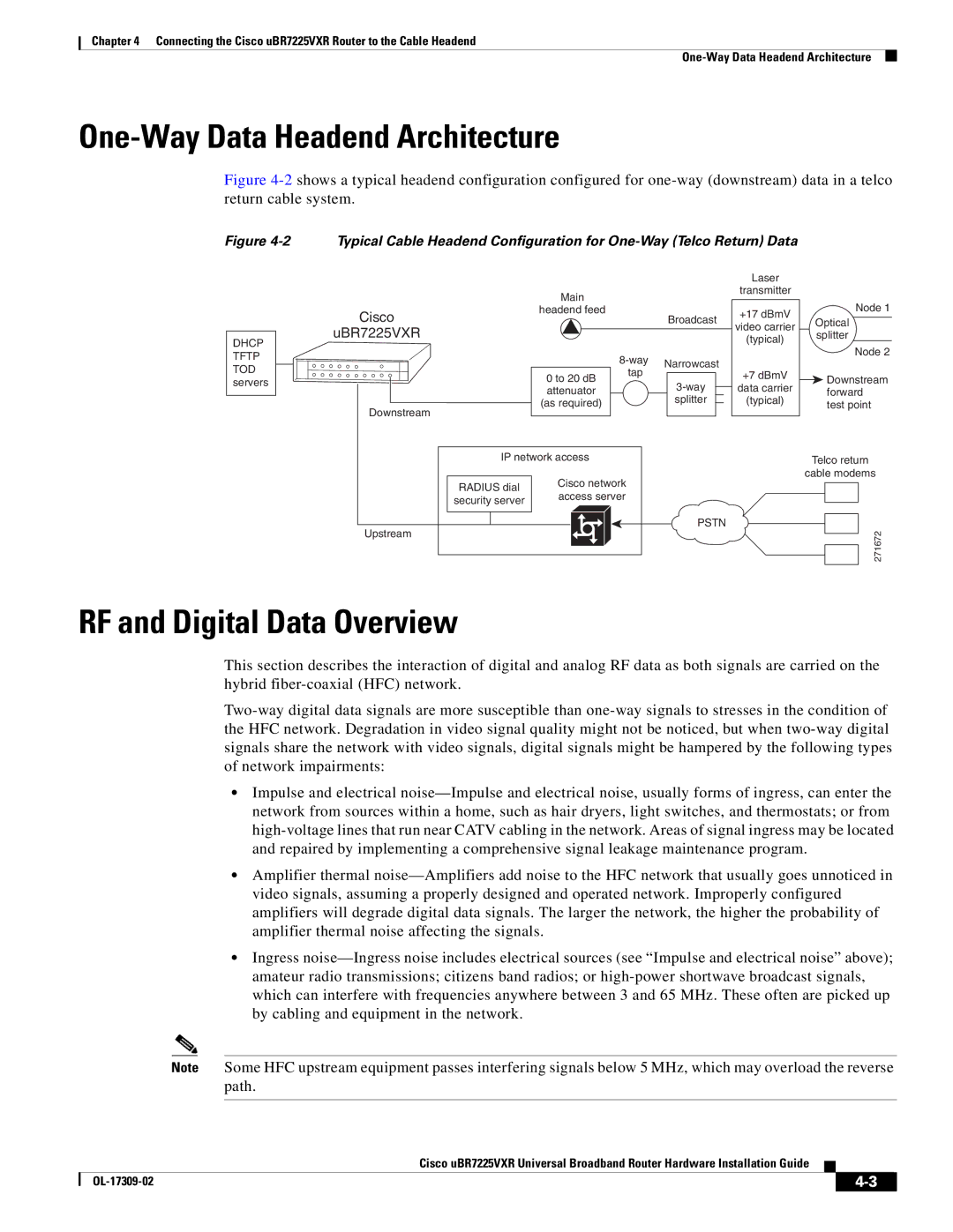
Figure 4-2 shows a typical headend configuration configured for one-way (downstream) data in a telco return cable system.
Figure
Typical Cable Headend Configuration for
DHCP TFTP TOD servers
Cisco
uBR7225VXR
Downstream
Main
headend feed
Broadcast
| Narrowcast | ||||||
0 to 20 dB |
| tap |
|
|
|
| |
|
|
|
|
|
| ||
attenuator |
|
|
|
|
|
| |
|
|
|
|
|
| ||
|
|
|
| splitter |
|
| |
(as required) |
|
|
|
|
|
| |
|
|
|
|
|
|
| |
|
|
|
|
|
|
|
|
Laser
transmitter
+17 dBmV
video carrier
(typical)
+7 dBmV
data carrier
(typical)
Node 1
Optical
splitter
Node 2
![]() Downstream forward test point
Downstream forward test point
IP network access | Telco return | |
| Cisco network | cable modems |
RADIUS dial |
| |
access server |
| |
security server |
| |
|
| |
Upstream |
| PSTN |
| 271672 | |
|
| |
RF and Digital Data Overview
This section describes the interaction of digital and analog RF data as both signals are carried on the hybrid
•Impulse and electrical
•Amplifier thermal
•Ingress
Note Some HFC upstream equipment passes interfering signals below 5 MHz, which may overload the reverse path.
Cisco uBR7225VXR Universal Broadband Router Hardware Installation Guide
|
|
| |
|
|
