Chapter 4 Connecting the Cisco uBR7225VXR Router to the Cable Headend
Measuring the Upstream RF Signal
Note Refer to the documentation that accompanied your particular spectrum analyzer for detailed instructions on activating and positioning the trigger line.
A known workaround exists for the Agilent 8591C spectrum analyzer. After activating and positioning the trigger line in video mode, you must press the “video” button on the spectrum analyzer once more to enable proper functionality.
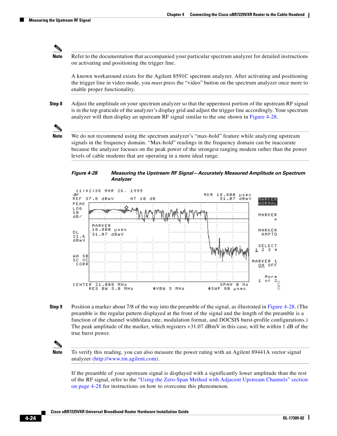
Step 8 Adjust the amplitude on your spectrum analyzer so that the uppermost portion of the upstream RF signal is in the top graticule of the analyzer’s display grid and adjust the trigger line accordingly. Your spectrum analyzer will then display an upstream RF signal similar to the one shown in Figure
Note We do not recommend using the spectrum analyzer’s
Figure 4-28 Measuring the Upstream RF Signal—Accurately Measured Amplitude on Spectrum Analyzer
Step 9 Position a marker about 7/8 of the way into the preamble of the signal, as illustrated in Figure
Note To verify this reading, you can also measure the power rating with an Agilent 89441A vector signal analyzer (http://www.tm.agilent.com).
If the preamble of your upstream signal is displayed with a significantly lower amplitude than the rest of the RF signal, refer to the “Using the
| Cisco uBR7225VXR Universal Broadband Router Hardware Installation Guide |
|