Chapter 4 Connecting the Cisco uBR7225VXR Router to the Cable Headend
Measuring the Upstream RF Signal
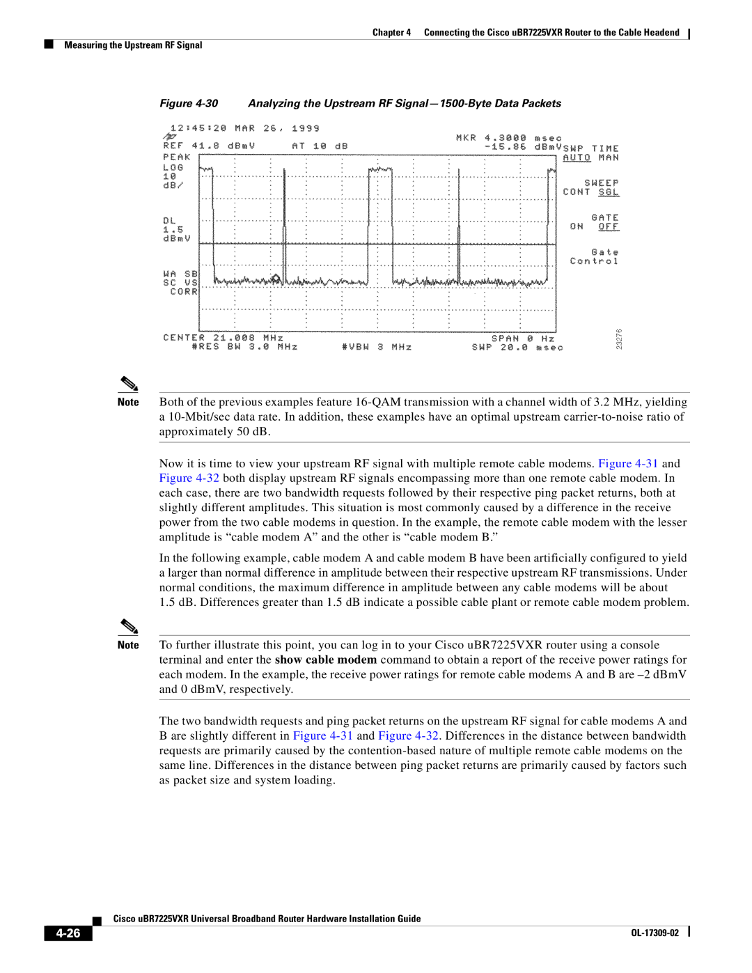
Figure 4-30 Analyzing the Upstream RF Signal—1500-Byte Data Packets
Note Both of the previous examples feature
a
Now it is time to view your upstream RF signal with multiple remote cable modems. Figure
In the following example, cable modem A and cable modem B have been artificially configured to yield a larger than normal difference in amplitude between their respective upstream RF transmissions. Under normal conditions, the maximum difference in amplitude between any cable modems will be about
1.5 dB. Differences greater than 1.5 dB indicate a possible cable plant or remote cable modem problem.
Note To further illustrate this point, you can log in to your Cisco uBR7225VXR router using a console terminal and enter the show cable modem command to obtain a report of the receive power ratings for each modem. In the example, the receive power ratings for remote cable modems A and B are
The two bandwidth requests and ping packet returns on the upstream RF signal for cable modems A and
Bare slightly different in Figure
| Cisco uBR7225VXR Universal Broadband Router Hardware Installation Guide |
|