Chapter 4 Connecting the Cisco uBR7225VXR Router to the Cable Headend
Measuring the RF Signal at the Forward Test Point on a Laser Transmitter
Note The slight
Figure 4-43 shows a smooth and easily measured signal amplitude, providing accurate measurement of a very fast burst upstream carrier. You can compare the measurements obtained using a spectrum analyzer with those of specialized test equipment. In general, the readings from the spectrum analyzer will be within 1 to 2 dB of the (more expensive) specialized equipment. Because 1 to 2 dB is well within the calibration accuracy of spectrum analyzers, you can reliably use these procedures in the cable headend environment.
Measuring the RF Signal at the Forward Test Point on a Laser Transmitter
This section describes RF signal measurements that should be taken with a spectrum analyzer at the downstream forward test point on the
Use the following steps to measure the downstream forward test point on the
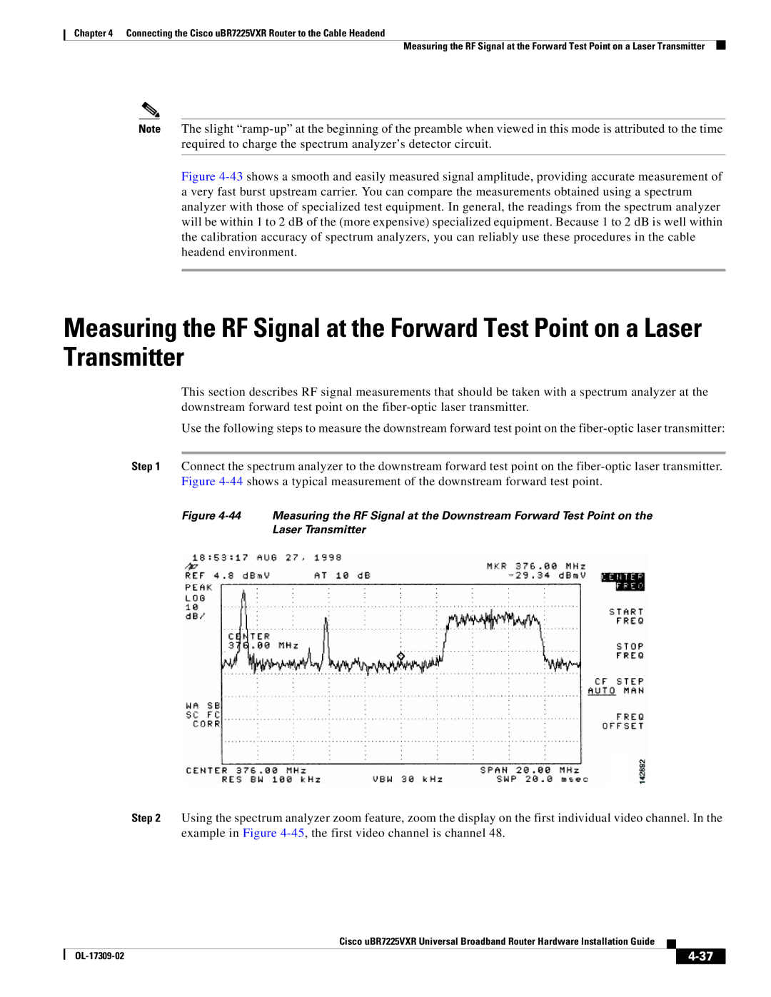
Step 1 Connect the spectrum analyzer to the downstream forward test point on the
Figure 4-44 Measuring the RF Signal at the Downstream Forward Test Point on the
Laser Transmitter
Step 2 Using the spectrum analyzer zoom feature, zoom the display on the first individual video channel. In the example in Figure
|
| Cisco uBR7225VXR Universal Broadband Router Hardware Installation Guide |
|
| |
|
|
| |||
|
|
|
|
| |
|
|
|
| ||