Chapter 4 Connecting the Cisco uBR7225VXR Router to the Cable Headend
Measuring the Upstream RF Signal
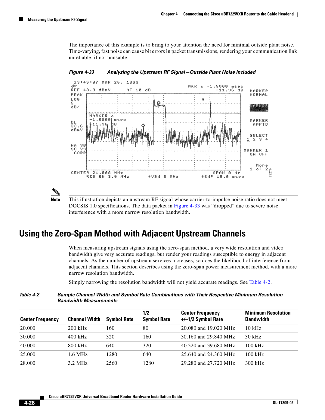
The importance of this example is to bring to your attention the need for minimal outside plant noise.
Figure 4-33 Analyzing the Upstream RF Signal—Outside Plant Noise Included
Note This illustration depicts an upstream RF signal whose
Using the Zero-Span Method with Adjacent Upstream Channels
When measuring upstream signals using the
Simply narrowing the resolution bandwidth will not yield accurate readings. See Table
Table | Sample Channel Width and Symbol Rate Combinations with Their Respective Minimum Resolution | |||||
| Bandwidth Measurements |
|
|
| ||
|
|
|
|
|
|
|
|
|
|
| 1/2 | Center Frequency | Minimum Resolution |
Center Frequency | Channel Width | Symbol Rate | Symbol Rate |
| Bandwidth | |
|
|
|
|
|
|
|
20.000 |
| 200 kHz | 160 | 80 | 20.080 and 19.020 MHz | 10 kHz |
|
|
|
|
|
|
|
30.000 |
| 400 kHz | 320 | 160 | 30.160 and 29.840 MHz | 30 kHz |
|
|
|
|
|
|
|
40.000 |
| 800 kHz | 640 | 320 | 40.320 and 39.680 MHz | 100 kHz |
|
|
|
|
|
|
|
25.000 |
| 1.6 MHz | 1280 | 640 | 25.640 and 24.360 MHz | 100 kHz |
|
|
|
|
|
|
|
28.000 |
| 3.2 MHz | 2560 | 1280 | 29.280 and 27.720 MHz | 300 kHz |
|
|
|
|
|
|
|
| Cisco uBR7225VXR Universal Broadband Router Hardware Installation Guide |
|